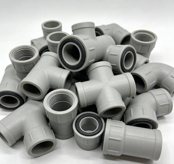
Water inlet elbow mold

Water Inlet Elbow Mold: The Manufacturing Core of Pipeline Connections
I. Product Definition and Functional Characteristics
The water inlet elbow mold is specialized molding equipment used to produce key connecting components that change fluid direction in pipeline systems. The elbows produced by these molds play a vital role in directional change connections within various piping systems. Their quality directly affects the sealing performance, fluid transport efficiency, and long-term operational reliability of the pipeline system. Mold design and manufacturing must comprehensively consider multiple factors including product structural features, application environment requirements, and production efficiency to ensure the produced elbows meet the technical specifications of different application scenarios.
II. Key Elements of Mold Structure Design
1. Cavity Runner Design
The cavity design of an elbow mold must consider fluid dynamic characteristics. The inner wall radius of curvature is optimized based on fluid properties, with common specifications including 1.0D, 1.5D, and others. The runner cross-section is designed as a graduated structure, with inlet and outlet areas adjusted according to flow rate requirements. Flow guide structures are incorporated in the bend area to improve fluid flow and reduce local resistance losses.
2. Molding System Configuration
The mold uses a hot runner system with gates positioned on the straight pipe sections of the elbow. Runners employ a balanced layout to ensure uniform melt filling. The cooling system is arranged according to the elbow's structural characteristics, with additional cooling points in thicker wall areas. The venting system is properly positioned at the parting line and flow ends to ensure gases are effectively expelled during filling.
3. Demolding Mechanism Design
A suitable ejection system is designed for the elbow's specific structure. Rotating demolding mechanisms are used in threaded areas to ensure complete thread release. Auxiliary ejection mechanisms are installed in bend areas to prevent sticking. The ejection system uses a multi-point balanced layout for even force distribution, avoiding product deformation.
III. Manufacturing Process Control
1. Machining Accuracy Control
Cavities are machined using precision equipment, with critical dimensional accuracy controlled within ±0.05mm. Curved surfaces are machined with multi-axis equipment to achieve the required surface roughness. Mating surfaces require higher precision, with flatness and perpendicularity controlled within 0.02mm/100mm. Threaded areas use specialized cutting tools to ensure thread accuracy.
2. Surface Treatment Processes
Cavity surfaces undergo polishing, with appearance surfaces reaching mirror finish requirements and non-appearance surfaces receiving appropriate texture treatment. Moving component surfaces are hardened to improve wear resistance. Cooling channels receive anti-corrosion treatment to extend service life. All machined surfaces are cleaned to remove oil, grease, and contaminants.
3. Assembly and Debugging Standards
All parts are inspected before mold assembly to ensure dimensional and geometric tolerances meet requirements. Precision measuring tools are used during assembly to control positional accuracy of components. Parting surface contact is checked during trial closing, with gaps controlled within an acceptable range. Moving parts are debugged to ensure smooth operation without binding.
IV. Material Selection Requirements
1. Mold Material Selection
Cavities and cores use pre-hardened mold steel with hardness HRC 30-40. Moving parts like sliders and lifters use quenched steel with hardness HRC 48-52. Mold plates use high-quality structural steel to ensure sufficient rigidity. Guide pillars and bushes use high-carbon steel with surface treatment to improve wear resistance.
2. Plastic Material Application
Appropriate plastic materials are selected based on usage requirements. Water supply systems commonly use PP-R material for good heat and pressure resistance. Drainage systems may use PVC material for lower cost. Special applications use engineering plastics to meet specific performance requirements. Material shrinkage and flow characteristics are considered during selection to ensure molding quality.
3. Auxiliary Material Usage
Seals use oil- and heat-resistant rubber materials. Fasteners use high-strength standard components. Lubricants use specialized mold lubricating oil. Cooling media use softened water or specialized coolant.
V. Production Process Management
1. Injection Molding Process Setup
Appropriate barrel temperatures are set in 3-5 zones based on material properties. Injection pressure is determined by product structure and wall thickness, typically 60-100 MPa. Packing pressure and time are adjusted based on shrinkage. Cooling time is calculated from wall thickness to ensure adequate cooling.
2. Mold Temperature Control
Mold temperature is controlled in zones with different temperatures set for different areas. Temperature controllers precisely regulate temperature, with fluctuations within ±2°C. Cooling water flow is adjusted as needed to maintain stable cooling. Temperature control systems are regularly inspected to ensure proper operation.
3. Production Parameter Optimization
Optimal process parameters are determined through mold trials, establishing standard operating procedures. Key parameters are monitored during production, with adjustments made for abnormalities. Production data is recorded for quality analysis and process improvement. Mold condition is regularly assessed to develop maintenance plans.
VI. Quality Control Requirements
1. Dimensional Accuracy Inspection
Critical dimensions including angles, center distances, and wall thickness are checked using Coordinate Measuring Machines (CMM). Thread inspection uses Go/No-Go gauges to check fit accuracy. Sealing surfaces are inspected for flatness and surface roughness. Sampling inspection is conducted during mass production to monitor dimensional stability.
2. Appearance Quality Inspection
Product appearance is inspected under standard lighting, including surface finish and color uniformity. Checks are made for flash, sink marks, air traps, and other defects. Threaded areas are inspected for integrity, with no damage or missing threads. Markings and characters must be clear and accurately positioned.
3. Performance Test Verification
Pressure testing is conducted: holding specified pressure for a specified duration with no leakage. Burst pressure testing verifies structural strength. Thermal cycling testing verifies temperature adaptability. Long-term static pressure testing verifies durability.