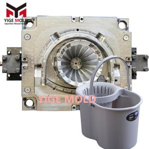
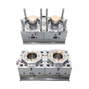
Hollowed turnover box mold

Technical Overview of Ventilated Turnover Box Molds
Ventilated (hollowed) turnover box molds are specialized equipment within the industrial injection molding sector, designed for manufacturing lightweight, high-strength logistics containers. Their core task is to form plastic containers featuring complex lattice structures, high specific strength, and functionalities such as stackability, anti-slip properties, and impact resistance. The primary design challenge lies in achieving substantial weight reduction through extensive ventilation (typically 25%-40%) while ensuring the overall rigidity and local compressive strength of the box, and simultaneously solving the process难题 of balanced melt flow and uniform filling within the dense rib grid network.
I. Structural Characteristics and Mold Design Response
-
Implementation of Grid-Based Lightweight Structure
The mold must form a continuous, regular array of cells (commonly hexagonal, square, or diamond-shaped) optimized for structural mechanics. The grid ribs typically have a width of 3-5mm and a height of 8-15mm. Their cross-sectional shape, often optimized via Finite Element Analysis (FEA), frequently adopts an "I-beam" or "T-shape" to enhance the moment of inertia against bending. Correspondingly, thousands of precise, identical protruding structures must be machined on the mold core. Achieving high dimensional accuracy, perpendicularity, and surface finish for these features represents a core manufacturing difficulty.
-
Local Reinforcement and Functional Integration Design
-
Rib Layout: In stress concentration areas such as the junctions between the box walls and bottom, and around hand holes, the mold provides reinforcement by locally increasing rib density or incorporating "crisscross" or radial stiffening ribs.
-
Anti-Slip Structure: On the box bottom and side grip areas, the mold cavity requires etching or engraving anti-slip patterns with a depth of 0.3-0.8mm. The pattern orientation must consider both draft angle and anti-slip performance.
-
Stacking Guidance Structure: Stacking alignment between upper and lower boxes often employs a conical post-and-socket design. The mold must precisely form the posts (typically 15-25mm high) with guide tapers and the corresponding sockets, controlling the unilateral fit clearance to 0.3-0.5mm.
-
-
High Complexity of the Ejection System
Due to the extensive rib and cell network on both the inner and outer product surfaces, the contact area with the mold is large, resulting in very high ejection resistance. The mold must employ a multi-point, multi-type ejection system:
-
In the large-area grid sections of the bottom, hundreds to thousands of small-diameter ejector pins (φ3mm-φ5mm) are densely placed beneath the rib intersections.
-
For deep, narrow grid sidewalls, special-shaped ejector blocks or blade ejectors are often designed. These act as part of the core during molding and push against the rib base during ejection.
-
To assist deep-cavity ejection, an integrated gas-assisted ejection system is common. During ejection, compressed air is injected between specific cores and the part to break the vacuum adhesion, allowing for smooth part release.
-
II. Special Design of Gating and Cooling Systems
-
Runner Balancing and Fill Control
Melt flowing through the dense rib network is highly prone to issues like hesitation, numerous and weak weld lines. Mold design must utilize:
-
Multi-point hot-to-cold runner gating: Multiple gate points (typically 4-8) are set at symmetrical locations on the box bottom or sidewalls, ensuring the melt fills each grid cell via the shortest flow path.
-
Sequential valve gate control: By controlling the opening sequence of individual gates, the melt front is guided along a predetermined path. This directs weld lines to non-critical stress areas or rib intersections and optimizes their strength.
-
-
Efficient but Non-Uniform Cooling Strategy
The grid structure creates a massive cooling surface area, but cooling the depths of the ribs is difficult. The cooling system design must follow a "differential management" principle:
-
In thick sections with dense ribs (e.g., grid intersection nodes), baffle-cooled bubblers, spiral cooling channels, or inserts of high thermal conductivity material (like beryllium copper alloy) are used to accelerate heat dissipation.
-
In large, thin-walled panel areas, conventional straight-through or surrounding cooling channels are arranged.
-
Each cooling circuit is independently controlled. By adjusting the water temperature and flow rate in each circuit, the uneven cooling rates caused by structural differences are balanced, minimizing internal stress and deformation to the greatest extent.
-
III. Mold Materials, Manufacturing, and Surface Treatment
-
Steel Selection
-
Main Molding Components: Due to the complex structure and fine ribs, steels with high hardness, toughness, and excellent polishability are required, such as mirror-finish mold steels like Sweden's ASSAB S136 or Japan's Daido NAK80, often used in pre-hardened condition to avoid heat treatment distortion.
-
Numerous Small Cores and Ejector Pins: For easier replacement and maintenance, these are often designed as insert structures, using more wear-resistant steels like carbide or powder metallurgy high-speed steel.
-
-
Precision Manufacturing Challenges
-
Machining of Numerous Precision Small Cores: The thousands of grid protrusions are produced via precision CNC milling, slow wire EDM, and micro-EDM, ensuring their shape consistency, dimensional accuracy, and positional precision.
-
Machining and Polishing of Deep, Narrow Rib Channels: The narrow slots between ribs (typically 3-5mm wide, over 10mm deep) require high-speed milling with small-diameter tools. Polishing the inner walls is extremely challenging, necessitating special tools and techniques.
-
Manufacture of Conformal Cooling Channels: For complex areas, metal 3D printing (SLM) technology may be used to manufacture inserts with integrated conformal cooling channels, optimizing cooling performance.
-
-
Surface Treatment
-
Cavity surfaces generally require a high finish (mirror or textured) to facilitate ejection and enhance product appearance.
-
Moving parts subject to frequent friction, such as ejector pins and sliders, undergo surface treatments like chrome plating, nitriding, or PVD coating to reduce the coefficient of friction and improve wear and galling resistance.
-
IV. Key Points in Mold Trial Debugging and Performance Verification
-
Core of Process Debugging
Focus is on multi-stage control of injection speed and pressure: initial slow fill to prevent jetting, medium-high speed to ensure complete filling of the complex grid, followed by appropriate packing to compensate for shrinkage in the rib areas. Mold temperature must be precisely controlled; excessively high temperatures can cause sink marks on ribs, while excessively low temperatures lead to short shots.
-
Common Defects and Countermeasures
-
Short Shot: Optimize gate location and size, increase injection speed/pressure, improve venting.
-
Prominent/Weak Weld Lines: Adjust gate timing sequence, optimize mold temperature, and if necessary, design "weld line reinforcement bosses" in critical areas.
-
Ejector Pin Blush, Cracking, or Warpage: Optimize the layout and balance of the ejection system, increase ejection area, utilize gas assistance, and adjust cooling uniformity.
-
-
Product Performance Verification
-
Stacking Test: Verifies the stability of multi-layer stacking under full load and the deformation of lower boxes.
-
Drop Test: Evaluates the impact resistance of the box at room temperature and low temperature.
-
Compression Test: Tests the load-bearing capacity and deformation recovery of the box under static and dynamic loads.
-
Conclusion
Ventilated turnover box molds represent the cutting-edge technology of injection molds in realizing structured, lightweight product design. Their success hinges on the协同 solution to a series of challenges: formability of complex rib-cell structures, overcoming immense ejection resistance, and achieving balanced filling of grid cells. This requires integrated simulation of mechanics and process from the design inception, precision machining of micro-structures during manufacturing, and mastery of the multi-factor coupled process window during debugging. The development of such molds not only drives logistics packaging towards lighter, stronger, and more environmentally friendly directions but also significantly elevates the comprehensive technical level of the mold industry in complex system design, precision manufacturing, and process control. The technical expertise gained is widely applicable to the production of plastic parts requiring high-strength ventilated structures, such as automotive components, appliance housings, and storage racks.