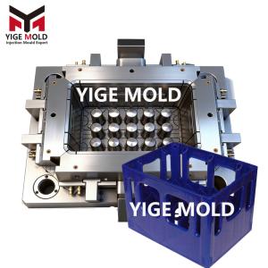
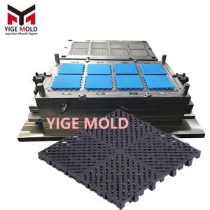
Frozen meat crate mold

Detailed Engineering Description of Frozen Meat Crate Molds
Frozen meat crate molds are a significant branch of heavy-duty industrial injection molds, specifically designed for producing plastic containers that handle the transportation and storage of meat within cold chain logistics systems. These molds must simultaneously meet the combined requirements of extreme temperature resistance (-30°C to 70°C), high load-bearing capacity (static load ≥ 500kg), and stringent hygiene standards, all within the structural characteristics of deep cavities, thin walls, and large dimensions. Their technical realization depends on the deep integration of structural mechanics, thermodynamics, and polymer materials science.
I. Mold Design Countermeasures for Extreme Operating Conditions
-
Achieving Low-Temperature Impact Resistance:
-
The mold employs variable wall thickness design. While maintaining a standard wall thickness of 3.5mm for the main body of the crate, it progressively increases to 5mm at the four corners and the intersections of the bottom ribs, creating gradient impact-resistant zones. Rib design utilizes a trapezoidal cross-section that is "wide at the base, narrow at the top" (base: 2.5mm, top: 1.8mm), ensuring smooth stress transfer along the ribs during low-temperature drops to avoid brittle fracture.
-
The bottom non-slip structure uses a composite texture design: macroscopically, it consists of 1.0mm deep wave patterns for forklift tine grip; microscopically, it is overlaid with a 0.2mm deep cross-hatch pattern to enhance slip resistance under wet conditions. This texture is achieved on the mold cavity through a combined process of CNC engraving and chemical etching.
-
-
Stacking Stability Structure Design:
-
The interlocking structure at the crate's upper rim is key to stacking stability. The mold must form a three-stage precision fit structure:
-
Guide Ramp: A 15° outward sloping surface for quick alignment of stacked crates.
-
Main Interlocking Surface: A 12mm high vertical mating surface with a unilateral clearance of 0.25mm.
-
Limit Flange: A 3mm wide annular shoulder that bears the full weight of the upper crate.
-
-
To enable demolding of this deep-cavity undercut structure, the mold uses a multi-layer slider core-pulling mechanism driven by hydraulic cylinders. Four main sliders form the outer walls, while four internal sub-sliders, under precise sequential control from the cylinders (sequence controlled by mechanical valves), first retract inward to release the undercuts before the main sliders move outward.
-
-
Hygienic Cleanability Design:
-
All internal corners of the mold cavity are designed with a radius of R3 or greater, eliminating any dead angles. The surface undergoes progressive manual polishing from 400# to 3000# grit sandpaper, finally achieving a mirror finish (Ra ≤ 0.2μm), resulting in a smooth inner crate surface that is easy to clean thoroughly.
-
The crate bottom is designed with an integral slope (approx. 1.5° gradient) converging towards the drain hole. This slope is ensured by the large angled machining of the mold core, guaranteeing complete liquid runoff.
-
II. Core Engineering Systems of the Mold
-
High-Strength, Rigid Mold Base System:
-
Total mold weight often reaches 15-25 tons. The mold base uses solid, pre-hardened steel plates (e.g., S50C), with plate thickness increased by over 30% to withstand the immense injection pressure (typically requiring 800-1500 tons of clamping force). Guide pillar diameter is increased to φ80mm-φ100mm and incorporates a tapered locating structure, ensuring mold closing accuracy within 0.1mm to prevent flash.
-
-
Large, Complex Runner and Gating System:
-
Due to the high product weight (5-8kg of plastic per crate), a hybrid "hot runner + cold runner" system is commonly used. The main flow channel uses large-diameter hot runners (e.g., φ25mm) to reduce pressure loss; before entering the cavity, it transitions to cold runners with precisely calculated cross-sectional areas to balance multiple melt flows.
-
Gates are often designed as submarine (tunnel) gates or direct sprue gates. Submarine gates shear off automatically for better appearance; direct sprue gates allow faster fill speeds, suitable for materials like PP with good flow. Gate locations are typically at the center of the crate bottom or the middle of the long side, facilitating radial flow of the melt.
-
-
High-Efficiency, Non-Uniform Cooling System:
-
This is one of the greatest design challenges. Wall thickness varies significantly across the crate, leading to different cooling needs. The system uses a "zonal independent circulation" design:
-
Thick-walled areas (e.g., corners, rib roots): Dense cooling channels are arranged, with pipe centers about 1.5 times the pipe diameter from the cavity surface, using spiral channels or baffled water wells for enhanced cooling.
-
Large thin-walled areas: Relatively straight but comprehensive water channels are arranged.
-
Each circuit has independent inlets and outlets, allowing connection to multiple mold temperature controllers on the injection molding machine. This enables differentiated temperature control for different zones (temperature differences up to 20-30°C) to coordinate cooling rates, reducing internal stress and warpage.
-
-
-
Multi-Component Coordinated Ejection System:
-
The ejection system is exceptionally complex, often comprising hundreds of ejector pins, blocks, and lifters.
-
Large Bottom Area: Dozens of φ8mm-φ12mm round ejector pins are uniformly distributed, and ejector blades may be used to eject the rib grid.
-
Deep Cavity Sidewalls: Due to small draft angles (often 0.5°-1°), pneumatic or hydraulic ejection assistance is required. In the later stage of ejection, compressed air is injected between the part and the core to aid release, preventing deformation or "ejector pin blush" caused by vacuum adhesion.
-
Local Undercuts or Threads (e.g., drain plug hole): Require the design of small angled lifters or unscrewing mechanisms.
-
III. Manufacturing Processes and Specialized Machining
-
Precision Machining of Large Cavities:
-
Cavity blocks (often weighing several tons) undergo roughing and finishing on large 5-axis machining centers or gantry mills. Due to their size, controlling thermal deformation during machining is critical, employing strategies like low speed, deep cuts, and ample cooling.
-
The high surface finish requirement for cavities necessitates hundreds of hours of manual polishing by skilled mold makers, using a progression of tools from stones and sandpaper to diamond paste.
-
-
Manufacturing of Complex Sliders and Core-Pulling Mechanisms:
-
Slider assemblies have complex structures requiring precision milling, jig grinding, and EDM. The mating angled surfaces (lock faces) between sliders and the core/cavity require hand scraping or lapping in pairs to ensure no flash under high pressure. The sliding guide surfaces of sliders need to be hardened and precision ground.
-
-
Heat Treatment and Surface Hardening:
-
Large core/cavity inserts typically use pre-hardened steels (hardness HRC 30-40) to avoid distortion risks from through-hardening. However, key wear areas (e.g., sliding surfaces of sliders, lifters) can be locally hardened using flame hardening, induction hardening, or laser surface hardening to achieve hardness above HRC 55.
-
To extend mold life, cavity surfaces may undergo nitriding or PVD coating to improve surface hardness and corrosion resistance.
-
IV. Mold Trial, Validation, and Production Debugging
-
Trial Preparation: Due to the mold's large size, a 500-ton or larger injection molding machine is required. All water, oil, and air line connections must be carefully checked for leaks before debugging.
-
Process Parameter Exploration: A "low to high" principle is applied. Key parameters to optimize include melt temperature (e.g., 190-230°C for HDPE), injection speed (slow initially to avoid jetting, then faster), and multi-stage injection/packing pressure and time. Packing is crucial for minimizing sink marks on large flat areas.
-
Key Problem Resolution:
-
Warpage: The most common issue. Addressed by adjusting cooling water temperature differences, packing pressure profiles, and mold temperature balance. Sometimes, warpage compensation (reverse bending) needs to be machined into the mold.
-
Sink Marks: Appear behind ribs or in thick sections. Addressed by enhancing local cooling, optimizing packing, or, if allowed, modifying product rib thickness (not exceeding 60% of the main wall thickness).
-
Ejector Pin Blush or Cracking: Optimized by balancing the ejection system, increasing the number or area of ejectors, or using assisted air ejection.
-
-
Functional and Durability Testing:
-
Stacking Test: Loaded crates are stacked to the required height (e.g., 5 high) and left for 24-72 hours. Deformation of the lower crates is checked against allowable limits (typically ≤1% height change).
-
Drop Test: Empty and loaded crates are dropped from a specified height (e.g., 1 meter) at different angles in a -25°C environment to check for cracking.
-
Fatigue Test: Simulates actual use through repeated stacking, handling, and washing cycles to evaluate the durability of moving parts like hinges and latches.
-
Conclusion
The design and manufacturing of frozen meat crate molds exemplify the application of mold technology in the field of heavy-duty industrial packaging. They successfully translate the performance requirements for extreme physical conditions (low temperature, heavy load) into a series of specific mechanical structure designs, material selections, and processing solutions. Their technical core lies not in a single breakthrough but in the systematic trade-off and engineering realization of interrelated and often conflicting factors: structural strength, thermal balance, demolding feasibility, production efficiency, and the mold's own service life. A successful mold is the crystallization of design theory, precision manufacturing, and extensive practical experience. It ensures the reliable, efficient, and economical production of this fundamental yet critical container in cold chain logistics, thereby supporting the stable operation of the modern food supply chain. Its technical challenges and solutions provide a valuable reference paradigm for the development of other molds for large, deep-cavity, high-demand industrial containers.