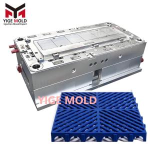
Plastic Grid Mold

Plastic Grid Mold: Industrial Framework of Three-Dimensional Interweaving
Opening: The Materialization of Reticular Forms
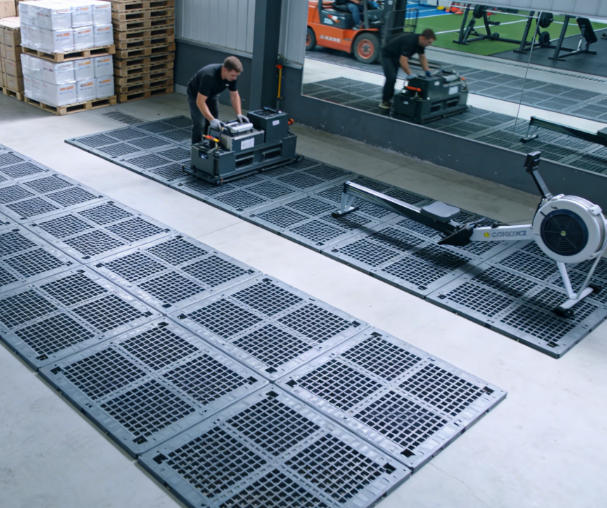
In numerous fields such as industrial filtration screens, architectural partitions, automotive grilles, and agricultural ground nets, plastic grids display a unity of function and aesthetics through their unique interwoven structures. The plastic grid mold, as the core production equipment for realizing this three-dimensional intersecting network, must transform planar design concepts into physical structures with spatial depth. This mold system must not only solve the precise forming of lines but also address a series of technical challenges including maintaining the strength of intersecting nodes, controlling batch uniformity of mesh openings, and achieving smooth demolding of three-dimensional structures.
I. Three-Dimensional Design of the Network Structure
1. Spatial Construction of the Grid System
Mold design requires laying out the grid in three-dimensional space:
Three-Dimensionalization of the Base Grid: The mold design for a standard orthogonal grid uses a layered structure. The longitudinal and transverse lines are not formed in the same plane but create a three-dimensional intersection through a height differential. Typically, longitudinal lines are on the upper plane, and transverse lines are on the lower plane, with a layer spacing of 0.6-0.8 times the line diameter. At intersection points, connecting posts are formed, with a post diameter 1.2-1.5 times the line diameter and a height equal to the layer spacing. This design ensures both visual transparency and increased structural rigidity.
Special Treatment for Diagonal Grids: 45-degree diagonal grids require adjustment of the mold opening direction. The line direction is at a 45-degree angle to the opening direction, necessitating a dual draft angle design for each line: 0.5 degrees along the line direction and 0.3 degrees perpendicular to it. Intersection nodes use a spherical connection, with a sphere diameter 1.8-2.0 times the line diameter, and the sphere center located on the mid-plane between the two grid layers. Vent holes are machined at the nodes, diameter Φ0.3-0.4 mm.
Adaptability for Graduated Grids: Grids that graduate from the center to the edges require variable parameter design. The grid size is smaller in the center, with a line width of 1.0-1.2 mm; larger at the edges, with a line width of 1.5-2.0 mm. The mold achieves dimensional graduation through adjustable inserts. Inserts are divided radially into 8-12 adjustment segments, with a width change rate of 5-8% per segment. The intersection angles of the lines also change accordingly, graduating from 90 degrees at the center to 100-110 degrees at the edges.
2. Multi-Dimensional Assurance of Structural Strength
The strength of a three-dimensional grid requires design from multiple dimensions:
Optimization of Line Cross-Section: Grid lines use a variable cross-section design. Straight sections use a rectangular cross-section with an aspect ratio of 1:1.5 to 1:2.0. Near node areas, it gradually changes to an oval shape, with the major axis along the line direction and a major-to-minor axis ratio of 1.2:1 to 1.5:1. The line surface has longitudinal reinforcing ribs, with a rib height 10-15% of the line height, a rib width 20-25% of the line width, and a rib spacing 2-3 times the line width.
Mechanical Reinforcement of Nodes: Intersection nodes use multi-level reinforcement. Level 1 is the reinforcement of the connecting post itself, with a wall thickness 30-40% greater than the line. Level 2 is radial reinforcing ribs around the node, with a rib length 1.5 times the node radius and a gradually decreasing height. Level 3 is a circular reinforcing platform on the back of the node, with a platform diameter 1.2 times the node diameter and a platform height 20-25% of the line height.
Pre-Design for Anti-Deformation: Accounting for uneven in-plane shrinkage of the grid, the mold applies differential compensation. The compensation value is 1.6-1.8% in the line direction, 1.8-2.0% in the node direction, and 2.0-2.2% in the diagonal direction. The entire grid is pre-set with a spherical curvature of 0.1-0.2 mm: slightly convex in the center and slightly concave at the edges, to counteract deformation during use.
II. Technical Implementation of Mold Construction
1. Manufacturing Process for Three-Dimensional Cavities
Grid molds require machining complex interlocking structures in three-dimensional space:
Layered Electrode Machining: The three-dimensional structure of the grid requires layered electrode production. Electrodes for upper and lower lines are made separately, with an electrode thickness 1.5 times the line height. Node electrodes are made individually, using spherical or cylindrical designs. Electrode material is high-purity graphite. Roughing electrodes are undersized by 0.4 mm per side; finishing electrodes are undersized by 0.1 mm per side. Electrodes are fixtured using 5-axis positioning to ensure precise spatial angles.
Combined Core Technology: Grid molds use modular cores. Each grid cell corresponds to a core module, with module sizes ranging from 50×50 mm to 100×100 mm. Modules are located with tapered surfaces, taper 1:30, fit clearance 0.003-0.005 mm. Module material is high-hardness tool steel, heat-treated to HRC 54-58. Module surfaces are polished to a surface roughness Ra ≤ 0.2 µm.
Precision Assembly Process: Mold assembly is performed in a temperature-controlled room at 20°C ±0.5°C. First, the base frame is assembled, flatness ≤0.01 mm/500 mm. Then, core modules are installed, layer by layer from the center outward, checking flatness after each layer. Finally, sliders and ejection systems are installed, with all moving parts manually tested to ensure smooth motion.
2. Special Solutions for Venting and Cooling
Three-dimensional grid structures pose special requirements for venting and cooling:
Spatial Venting System: The mold has a 3D venting network. Horizontally, vents are machined on the parting line: depth 0.02-0.025 mm, width 6-8 mm. Vertically, vent holes are placed inside the core: diameter Φ0.8-1.0 mm, depth 5-8 mm greater than the grid height. Micro vent plugs made of sintered metal (porosity 25-30%) are placed at intersection nodes. The total venting area is 1.2-1.5% of the grid's projected area.
Differentiated Cooling Layout: Cooling channels are designed based on grid density. In high-density areas, channels are 10-12 mm from the cavity surface, diameter Φ10 mm, water velocity 2.0-2.5 m/s. In low-density areas, channels are 15-18 mm from the surface, diameter Φ12 mm, velocity 1.5-2.0 m/s. Node areas have point cooling using heat pipe technology, thermal conductivity ≥5000 W/m·K. Cooling water is controlled by zone, temperature difference between zones ≤2°C.
Temperature Gradient Management: The mold establishes a temperature gradient field. The grid center area is 55-60°C, the middle area 50-55°C, and the edge area 45-50°C. This gradient design facilitates sequential solidification of the melt from the center outward, reducing internal stress. Temperature control accuracy is ±1°C, with a gradient change rate ≤2°C/100 mm.
III. Spatial Movement of Demolding Mechanisms
1. Demolding Strategy for Three-Dimensional Structures
The three-dimensional interlocking of grids requires complex demolding actions:
Multi-Directional Sequential Core Pulls: Grid molds require sequential core pulls in multiple directions. First, the main vertical pull, stroke 20-30 mm, speed 30-50 mm/s. Then, auxiliary 45-degree pulls, stroke 15-20 mm, speed 20-30 mm/s. Finally, horizontal fine-adjustment pulls, stroke 5-8 mm, speed 10-15 mm/s. Core pulls have mechanical interlocks to ensure correct sequence.
Gas-Assisted Separation: Gas channels are placed on the back of grid nodes, channel diameter Φ0.4-0.5 mm, arranged in a star pattern. During demolding, 0.4-0.6 MPa compressed air is injected for 0.3-0.5 seconds. Gas pressure is controlled in stages: initial stage 0.2-0.3 MPa, middle stage 0.4-0.5 MPa, final stage 0.3-0.4 MPa. Gas actuation is precisely synchronized with mechanical ejection, timing error ≤0.05 seconds.
Flexible Ejection System: Ejector pins use a segmented design, with a rigid pin body connected via threads to a flexible pin head. Head material is engineering plastic, hardness Shore D 75-80. Ejection is in three stages: Stage 1 stroke 5-8 mm, speed 5-10 mm/s; Stage 2 stroke 10-15 mm, speed 20-30 mm/s; Stage 3 stroke 15-20 mm, speed 40-50 mm/s. Each stage has a 0.2-0.3 second dwell time after ejection.
2. Precision Guiding and Positioning
Three-dimensional molds have extremely high requirements for motion precision:
Compound Guiding System: The mold uses dual guiding. Main guides are square pillars, section 40×40 mm, length 30% greater than standard. Secondary guides are round pillars, diameter Φ25 mm, placed at the four corners. Guide fit clearance is 0.006-0.010 mm, ensured by selective assembly. Guide surfaces are treated for hardness HRC 60+, wear life ≥1 million cycles.
Multi-Stage Positioning Mechanism: A three-level positioning system is used. Primary positioning uses tapered surfaces, taper 1:15, positioning accuracy ±0.005 mm. Secondary positioning uses angled surfaces, angle 10 degrees, accuracy ±0.003 mm. Tertiary positioning uses pin/hole, pin diameter Φ8h6, hole diameter Φ8H7, accuracy ±0.002 mm. Each level has wear compensation devices.
Motion Synchronization Control: Multiple motion mechanisms are synchronized via mechanical linkage, using rack and pinion sets (module 2, accuracy grade 6). Synchronization detection sensors monitor position deviation of moving parts, automatically adjusting if deviation ≥0.01 mm. Motion speed is precisely controlled via hydraulic throttle valves, flow control accuracy ±2%.
IV. Ensuring Stability in the Production Process
1. Precise Control of Process Parameters
Grid molds require fine-tuning of molding parameters:
Multi-Stage Injection Control: The injection process is divided into 4-5 stages. Stage 1: 10-15% of shot volume, speed 20-30 mm/s, filling node areas. Stage 2: 30-40% of shot volume, speed 40-60 mm/s, filling main lines. Stage 3: 30-40% of shot volume, speed 60-80 mm/s, completing grid fill. Stage 4: 10-15% of shot volume, speed 20-30 mm/s, for packing. Injection pressure is graded accordingly, from 60 MPa gradually increasing to 100 MPa.
Variable Packing Pressure: Packing pressure changes over time. 0-5 seconds: 80-90% of injection pressure. 5-10 seconds: 70-80%. 10-15 seconds: 60-70%. After 15 seconds: maintained at 50-60%. Packing time is based on grid wall thickness: 8-10 seconds per mm. The switch point is controlled by cavity pressure sensors, switching when pressure reaches 95% of the set value.
Programmed Temperature Control: Mold temperature changes according to a program. After mold close, rapid heat-up to set temperature at 3-5°C/s. Maintain constant temperature during injection, fluctuation ≤±1°C. Slow cooling during packing at 0.5-1°C/s. Rapid cool-down to demolding temperature before mold open at 2-3°C/s. Barrel temperatures also change accordingly, with a front-to-rear difference of 10-15°C.
2. Systematic Methods for Quality Maintenance
Ensuring long-term stable mold production:
Periodic Accuracy Calibration: Perform accuracy calibration every 10,000 cycles. Use a CMM to inspect key grid dimensions: line width, node size, flatness, hole pitch, etc. Record and analyze inspection data, establishing accuracy trend charts. Perform preventive adjustment when deviation reaches 50% of the tolerance.
Wear Monitoring and Repair: Establish a wear monitoring system. Periodically measure dimensions of wear-prone areas: core height, slider clearance, ejector pin length, etc. Establish wear curves to predict component life. Repair wear using processes like brush plating or laser cladding, restoring accuracy to over 90% of original specification. Maintain replacement records to optimize spare parts inventory.
Systematic Maintenance Procedures: Develop detailed maintenance procedures. Daily maintenance includes cleaning, lubrication, and tightening, performed per shift. Weekly maintenance includes checking venting systems, cleaning cooling channels, inspecting electrical connections. Monthly maintenance includes comprehensive check of moving parts, measuring key dimensions, testing safety devices. Annual maintenance includes disassembly inspection, wear repair, and replacement of wear parts. All maintenance records are archived, establishing a mold health file.
Conclusion: The Industrial Narrative of Interwoven Structure
The plastic grid mold, this production system that transforms planar lines into a three-dimensional network, contains profound manufacturing technology within its interwoven structure. It must not only precisely replicate the shape of each mesh opening but also ensure the orderly arrangement of thousands of openings in three-dimensional space; it must not only achieve clear line formation but also ensure the firm connection of intersection nodes.
When plastic solidifies into a grid within the mold, we witness the transformation of material from flow to fixity, and more importantly, the transformation of structure from concept to entity. Each uniform mesh opening is the result of flow control; each firm node is the endpoint of pressure transfer; each successful demolding is a victory of precise motion.
In an era where grid structures are increasingly important, the plastic grid mold, with its unique technical language, participates in constructing modern industry's filtration systems, architectural dividing interfaces, and transportation protection structures. In this interconnected world, this mold system, with its rigorous engineering logic, weaves the symphony of function and form, interpreting manufacturing technology's ability to master complex structures.