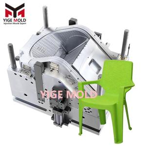
Office Chair Five-Point Star Base Mold


Introduction to Office Chair Five-Star Base Molds
I. Overview of the Office Chair Five-Star Base
1.1 Definition and Characteristics of the Five-Star Base
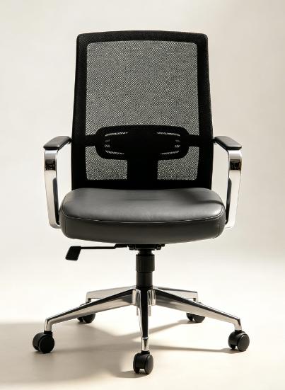
The office chair five-star base is, as the name implies, the supportive structure at the bottom of an office chair characterized by its distinctive five-legged shape. It serves as the foundation that firmly supports the entire chair body. By definition, it is a critical component responsible for connecting the seat to the ground and bearing the user's weight.
The characteristics of the five-star base are distinct:
-
Stability: This is its primary feature. The five-point design distributes pressure evenly, ensuring the chair remains steady even under sudden external forces or impact. This significantly enhances user safety and prevents tipping.
-
Flexibility: Typically paired with swivel casters (wheels), the base allows users to move and turn the chair effortlessly. This improves work efficiency and reduces physical strain when adjusting positions or reaching for items.
-
Durability: Generally constructed from high-strength materials such as quality metals or engineering plastics, the base possesses excellent deformation resistance and anti-aging properties, providing a solid guarantee for the chair's long-term use.
1.2 Importance of the Five-Star Base in Office Chairs
The five-star base holds a pivotal position in office chair design, directly impacting stability and comfort.
-
Stability: Acting as the chair's "foundation," the five-star structure ensures the center of gravity remains balanced, preventing accidents caused by instability. In office environments requiring prolonged concentration, a stable base is fundamental to productivity.
-
Comfort: In conjunction with casters, it allows users to adjust their posture and position easily, reducing fatigue associated with static sitting. Furthermore, the base provides a robust platform for attaching other functional components like adjustable backrests and armrests, thereby enhancing the overall ergonomic value and practicality of the chair.
II. Structure and Design of Office Chair Five-Star Base Molds
2.1 Main Components of the Mold
The mold consists of several key parts:
-
Fixed Half (Cavity Side): Includes the fixed clamping plate and cavity insert, which define the external shape of the base.
-
Moving Half (Core Side): Includes the moving clamping plate and core insert, mating with the cavity to form the complete mold cavity.
-
Guide System: Components like guide pillars and bushes ensure precise alignment during mold opening and closing.
-
Ejection System: Consists of ejector pins and the ejector plate, responsible for pushing the finished part out of the mold.
-
Cooling System: Waterlines and channels that regulate mold temperature to ensure quality and cycle efficiency.
-
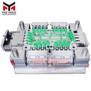
Gating System: The sprue, runners, and gate through which molten plastic enters the cavity.
2.2 Design Principles and Concepts
The design prioritizes product function and quality. It requires precise analysis of the base's structural features to meet dimensional accuracy requirements. Considering the flowability and shrinkage rate of the plastic material, the runner and gate systems are designed to ensure uniform filling and minimize defects. Efficiency is optimized by simplifying the mold structure and processing techniques. Maintainability is also considered, ensuring the mold is easy to disassemble for servicing. Advanced CAD/CAM technologies and mold flow analysis are employed to simulate and optimize the design, guaranteeing reliability for mass production.
2.3 Analysis of Key Design Elements
-
Material Selection: The hardness, strength, and wear resistance of the mold steel directly affect service life and product surface quality.
-
Structural Rationality: Improper placement of the parting line can cause flash and burrs.
-
Dimensional Accuracy: Precise matching of mold components is essential to prevent dimensional deviations in the product.
-
Surface Finish: The cavity surface must be finely machined to reduce roughness, affecting the product's appearance.
-
Cooling System Design: Uneven cooling water layouts can cause temperature imbalances, leading to internal stress and warpage in the final product.
III. Manufacturing Process of Office Chair Five-Star Base Molds
3.1 Material Selection and Treatment
High-quality alloy steels are commonly used due to their strength, hardness, and wear resistance.
-
Forging: Improves the internal microstructure, refines grains, and eliminates defects to enhance mechanical properties.
-
Annealing: Reduces hardness and relieves internal stresses from forging, facilitating subsequent machining and ensuring dimensional stability.
3.2 Processing Flow and Equipment
The journey from raw material to finished mold involves:
-
Rough Machining: Using CNC milling machines to remove excess material and establish the basic shape.
-
Semi-Finish Machining: Utilizing machining centers to improve dimensional accuracy and surface finish.
-
Finish Machining: Employing high-precision CNC grinders and EDM (Electrical Discharge Machining) to achieve final tolerances and surface quality.
-
Surface Treatment: Polishing and hard chrome plating to enhance surface hardness, wear resistance, and corrosion resistance.
Equipment used includes CNC mills, machining centers, grinders, EDM machines, and wire-cutting machines.
3.3 Quality Control and Inspection
Strict QC is enforced throughout:
-
Material Inspection: Verifying chemical composition and mechanical properties upon arrival.
-
In-Process Inspection: Self-checking and mutual-checking at each stage for dimensions and surface roughness.
-
Precision Measurement: Using Coordinate Measuring Machines (CMM) to verify critical dimensions.
-
Visual Inspection: Checking for cracks, burrs, or surface defects.
-
Trial Run (T0): Testing the mold on an injection machine to check for flashing, sink marks, or ejection issues, followed by necessary adjustments.
IV. Market and Applications of Office Chair Five-Star Base Molds
4.1 Market Demand Analysis
With the continuous expansion and renovation of office spaces, the demand for office chairs—and consequently their molds—is rising steadily. Modern chairs emphasize comfort and aesthetics, driving diversification in base materials, shapes, and functions. This trend pushes the mold market toward customization. Companies' focus on production efficiency and cost control favors high-precision, high-performance molds, compelling the industry to innovate constantly.
4.2 Application Areas and Cases
-
Corporate Offices: High-volume production molds supply stable, durable bases for employee workstations. (Case: A large enterprise utilized molds with advanced工艺 to produce bases that significantly improved employee experience).
-
Educational Institutions: Schools and libraries require bases that are safe and comfortable for student use.
-
Government Agencies: Focus on molds producing dignified, reliable, and high-quality bases to match formal environments. (Case: A government agency praised the durability of chairs produced from strictly controlled molds).
4.3 Development Prospects and Challenges
-
Prospects: Increasing demand for high-quality, personalized office furniture promises market growth. New materials (composites) and technologies offer opportunities to reduce costs and improve performance.
-
Challenges: Intense market competition compresses profit margins. Stricter environmental regulations increase production costs. The pressure to innovate requires continuous R&D investment to meet the demand for higher precision and performance.
V. Maintenance and Care of Office Chair Five-Star Base Molds
5.1 Daily Maintenance Points
-
Cleaning: Remove plastic residue and debris from the mold surface before and after use to prevent damage to the parting line and precision.
-
Inspection: Regularly check the tightness of bolts and connectors.
-
Temperature Control: Monitor mold temperature via the cooling system to prevent overheating or overcooling.
-
Lubrication: Lubricate moving parts (guide pillars, ejector pins) regularly to reduce wear.
-
Storage: Store in a dry, ventilated environment and apply anti-rust oil when idle.
5.2 Common Faults and Troubleshooting
-
Flash: Caused by foreign matter on the parting line or excessive gaps. Solution: Clean the surface or adjust mold alignment.
-
Dimensional Deviation: Caused by worn cores/cavities. Solution: Repair or replace the damaged inserts.
-
Ejection Failure: Caused by stuck or broken ejector pins. Solution: Repair or replace components.
-
Overheating: Caused by blocked cooling channels. Solution: Clean the waterlines.
-
Short Shots/Sink Marks: Often related to insufficient injection pressure or poor venting. Solution: Adjust parameters or add vents.
5.3 Measures to Extend Service Life
-
Material: Select high-performance alloy steel with high hardness and strength.
-
Design: Optimize structure to avoid sharp corners and stress concentration.
-
Manufacturing: Use precision machining and surface hardening treatments (like nitriding).
-
Operation: Strictly follow operating procedures to avoid overloading the mold.
-
Maintenance: Conduct regular preventative maintenance to address minor issues before they escalate.