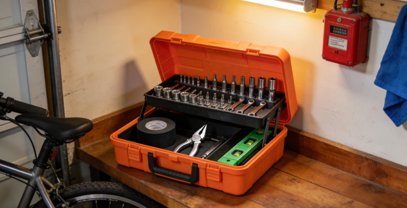
Tool Case Mold

 Tool Case Mold: Technical Analysis of Precision Structural Molding
I. Product Positioning and Technical Characteristics
Tool case molds are specialized precision molding equipment used to manufacture various tool storage containers with enhanced portability and protective features. Their technical core lies in addressing three major challenges: protective shell structure, integrated handle systems, and secure closure mechanisms. Unlike standard container molds, tool case molds must achieve robust impact resistance, ergonomic carrying design, and reliable sealing, placing them in the medium-complexity category of injection molds.
II. Key Structural Design Points
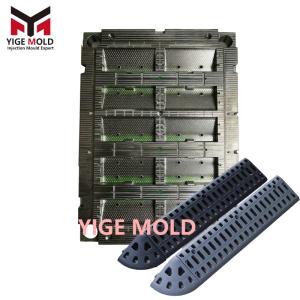
1. Protective Shell Molding
Adopts a balanced layout design of 1x2 cavities for optimal structural integrity. Gate locations are optimized through mold flow analysis to ensure case wall thickness uniformity is controlled within ±0.12mm. Rib structures utilize a hybrid grid pattern, with rib height to wall thickness ratio of 3.5:1. Edge protection features incorporate radiused corners with R5-R8 dimensions.
2. Integrated Handle and Closure Systems
-
Carrying System: Employs dual-material injection molding with reinforced nylon cores and soft-grip TPE overmolds. Stress distribution is optimized through finite element analysis to support 25-30kg dynamic loads.
-
Latching Mechanism: Multi-point locking systems feature stainless steel insert molding, with engagement tolerances controlled within ±0.15mm. Compression seals provide IP54 level protection against dust and moisture ingress.
-
Hinge Design: Continuous piano hinges or multiple independent hinge points are precision-molded with clearance gaps of 0.2-0.3mm for smooth operation over 10,000+ cycles.
3. Internal Organization Systems
Modular divider systems employ slide-in tracks with ±0.1mm dimensional consistency. Custom foam inserts are designed with laser-cut tool impressions, requiring specialized mold textures for anti-slip surfaces. Removable tray systems feature integrated handles and stacking features.
III. Material and Process Compatibility
1. Material Selection Schemes
-
Professional Models: Use ABS/PC blends with impact modifiers, featuring notched Izod impact strength ≥500 J/m.
-
Heavy-Duty Models: Employ structural foams with density gradients from 0.8-1.2 g/cm³ for optimal weight-to-strength ratio.
-
Specialty Models: Incorporate EMI/RFI shielding compounds for electronic tool cases, with surface resistivity ≤1.0 Ω/sq.
2. Molding Process Parameters
Melt temperatures are precisely controlled: ABS-based materials at 230-250°C, polypropylene copolymers at 200-220°C. Injection pressures utilize four-stage profiling: initial fill at 60-70MPa, secondary at 80-90MPa, packing at 50-60MPa, with holding pressure duration calculated as 1.8-2.2 seconds/mm wall thickness.
IV. Mold Manufacturing Technical Requirements
1. Steel Selection Standards
Primary cavity blocks use premium P20+Ni steel with hardness HRC 32-36. High-wear areas employ S7 tool steel with hardness HRC 58-60. Core pins and ejectors use H13 with titanium nitride coating for extended service life.
2. Machining Accuracy Control
Parting line flatness requirement: 0.015mm/300mm. Critical sealing surfaces achieve Ra 0.4-0.8 μm roughness. Moving component fits maintain 0.01-0.02mm clearance. Alignment features incorporate tapered interlocks with 0.5° draft angles.
3. Temperature Control System Design
Implements 12-zone temperature control with independent manifolds. High-mass areas use conformal cooling channels following 3D contours within 8-12mm of cavity surfaces. Temperature uniformity maintained within ±3°C across all zones during steady-state operation.
V. Venting and Ejection Systems
1. Venting Channel Layout
Perimeter venting employs land areas of 3-5mm with 0.015-0.025mm depth. Deep cavity sections incorporate porous metal inserts with 30-40% porosity. Critical cosmetic areas use vacuum venting systems with response time <0.5 seconds.
2. Ejection System Optimization
Ejector layout follows stress distribution patterns with pin diameters φ5-φ8mm. Undercut releases employ angle-lift mechanisms with 8-12° actuation angles. Ejection sequencing uses hydraulic core-pull for complex internal features before main ejection.
VI. Quality Inspection Standards
1. Dimensional Accuracy Inspection
Laser scanning verifies external contours within ±0.25mm tolerance. Wall thickness mapping using ultrasonic testing ensures uniformity within ±10%. Hinge alignment checked with optical comparators to 0.05mm parallelism.
2. Functional Test Items
-
Impact Resistance: 1.5-meter drop onto concrete with 15kg load, no functional damage.
-
Water Resistance: IP54 testing with 10L/minute water spray for 10 minutes, no ingress.
-
Cycle Testing: 15,000 open-close cycles with 10kg load, all functions operational.
-
Temperature Cycling: -30°C to 70°C for 20 cycles, dimensional stability within 0.2%.
3. Production Validation Requirements
Statistical process control monitors 15 critical dimensions with CPK ≥1.67. Material consistency verified through melt flow rate testing every 50 cycles. Color match maintained within ΔE 1.5 throughout production run.
VII. Production Efficiency Optimization
1. Rapid Changeover Design
Standardized mounting plates with quick-disconnect systems enable changeover in <20 minutes. Modular insert systems allow configuration changes in 2-4 hours. Hot runner systems feature cartridge-style heaters for 15-minute replacement.
2. Automation Compatibility
Integrated robot interfaces with standardized TCP points. Ejector plates include proximity sensors for position verification. Sprue pickers and conveyors are pre-aligned during mold design phase.
3. Maintenance Systems
Preventive maintenance schedule at 50,000 cycles includes guide post lubrication and wear inspection. Critical components feature RFID tags with service history tracking. Spare parts inventory optimized using failure mode analysis data.
VIII. Application Field Expansion
1. Professional Trade Applications
Electrician cases with integrated circuit testers and multimeter holders. Mechanic cases with wrench organizers and oil-resistant compartments. Construction cases with level vial holders and blueprint pockets.
2. Specialized Industrial Uses
Calibration cases with temperature-controlled compartments maintaining ±1°C. Inspection cases with shock-mounted instrument panels. Field service cases with integrated power supplies and data ports.
3. Military and Aerospace
MIL-STD-810G compliant cases with 100G shock resistance. EMP-protected cases with continuous Faraday cage construction. Pressure-equalized cases for altitude changes from sea level to 15,000 feet.
IX. Economic Performance Metrics
Tooling investment provides 500,000-750,000 cycle lifespan with <0.1% maintenance cost per cycle. Production rates achieve 45-60 second cycles for medium cases. Material utilization reaches 94-96% through optimized runner systems. Changeover time between colors or materials reduced to 15-25 minutes.
The evolution of tool case mold technology reflects advancing requirements for professional equipment protection and organization. From basic protective containers to intelligent equipment management systems, mold engineering continues to enable new levels of functionality and reliability. Future developments will further integrate electronic systems, environmental controls, and connectivity features, transforming tool cases into comprehensive equipment management platforms.