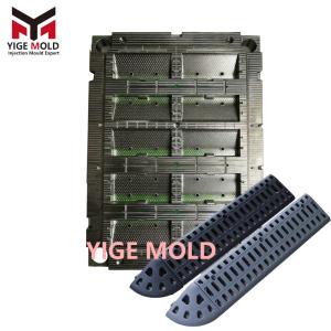
High stool mold
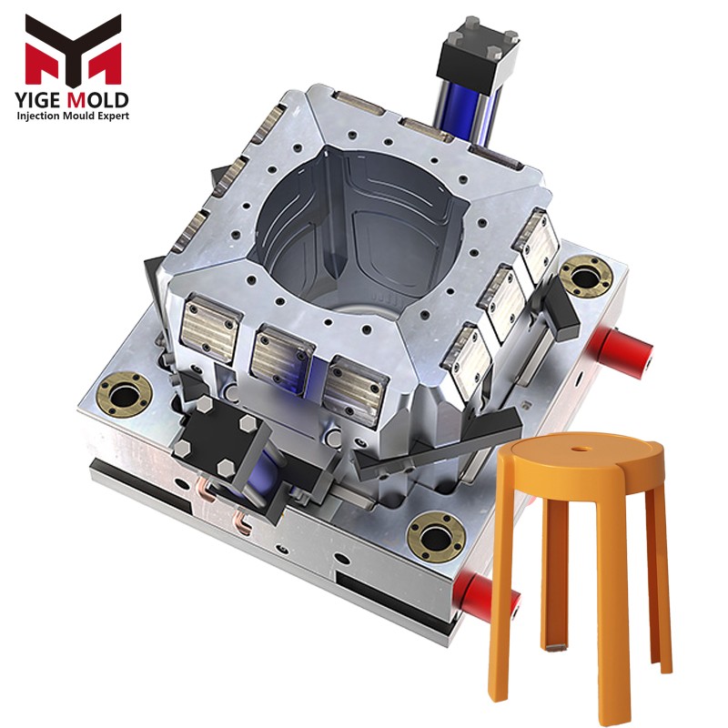
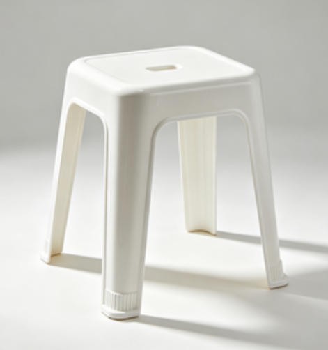
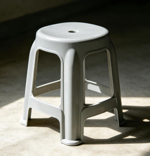
Technical Introduction to High Stool Injection Molds (Bar Stool Molds)
I. Overview and Application Background
The High Stool Mold, also known as the Bar Stool Injection Mold, is a precision tool specifically engineered for the mass production of plastic high stools, bar stools, and leisure seating via the injection molding process. Due to their elevated seat height (typically 60–90 cm from the ground) and structural features such as slender columns and ring-shaped footrests, high stools impose higher requirements on mold design regarding uniform filling, rib distribution, and balanced ejection compared to standard low stools. These molds are widely used in the industrial manufacturing of household goods, restaurant furniture, and commercial seating. Common materials for finished products include Polypropylene (PP), Acrylonitrile Butadiene Styrene (ABS), or Glass Fiber Reinforced Nylon (PA+GF).
High stool molds typically utilize single-cavity or double-cavity designs. Given the large projected area and substantial injection weight (usually 1.8–3.5 kg), they are generally paired with injection molding machines ranging from 650T to 1200T. The mold assembly consists of six core systems: the mold base, cavity/core components, gating system, cooling system, ejection system, and exhaust system. For models incorporating metal inserts or interference-fit footrest rings, side-core pulling (cam action) mechanisms or insert positioning structures are also required.
II. Product Structure and Molding Challenges
A typical high stool comprises three geometric features: a wide seat panel (often ergonomically curved with anti-slip textures), a central support column (thin-walled or with radial ribs), and diverging legs (usually four or five legs splayed at 8°–12° to prevent tipping). Key molding challenges include:
-
Wall Thickness Variation: Significant thickness differences between the seat and legs can cause uneven cooling, leading to warpage or sink marks. This necessitates regionally differentiated cooling channel layouts.
-
Deep Cavity and Core-Pulling: Cross-shaped reinforcing ribs inside slender columns often require detachable inserts or internal collapsible cores for demolding.
-
High Appearance Standards: Commercial bar stools often require leather-grain, wood-grain, or high-gloss textures. Cavity surfaces must undergo mirror polishing or specialized etching (EDM texturing), with no visible weld lines or flash allowed.
-
Stackability: Most high stools require vertical stacking for storage. Molds must strictly control the taper and dimensional tolerances of the seat flange (typically 1°–2° draft angle).
III. Overall Mold Structure
1. Mold Base System
Standard two-plate or three-plate mold bases are used, typically constructed from pre-hardened steel P20 (3Cr2Mo) after quenching and tempering. The fixed half contains the cavity plate, while the moving half comprises the core plate, support plate, ejector housing, and clamp plate. Four guide pillars and bushings ensure repeated positioning accuracy ≤ 0.01 mm during mold closing.
2. Cavity and Core Components
The Cavity shapes the outer surface (seat curvature, edge chamfers, texture), while the Core shapes the inner surface and hollow column walls. Critical forming parts are made from premium mold steels like 718H, NAK80, or S136, achieving hardness levels of HRC 30–36. Key surfaces are finished via high-speed CNC machining and Electrical Discharge Machining (EDM), achieving a surface roughness Ra ≤ 0.2 μm (mirror grade) or specific EDM textures as per customer requirements.
3. Gating System
Selection depends on output and appearance requirements:
-
Cold Runner: Trapezoidal or circular runners (Φ8–Φ12 mm) with fan gates or submarine gates. Suitable for cost-effective single-cavity production but requires manual degating.
-
Hot Runner: Open or valve-gated hot nozzles (e.g., Yudo, Husky brands). Multi-point sequential gating balances melt flow, reduces weld lines, and is ideal for large seat panels, offering near 100% material utilization.
Gate locations are strategically placed beneath the seat or at the column root in non-visible areas to avoid cosmetic defects.
4. Cooling and Temperature Control System
Efficient cooling is critical. The seat area experiences high thermal load and utilizes conformal cooling channels or dense parallel drilling (Φ10–Φ12 mm), positioned 12–18 mm from the cavity surface. The slender column zone features separate spiral or straight waterways for rapid heat dissipation. Mold temperature controllers are recommended; typical settings are 30–50°C for PP and 50–70°C for ABS. The inlet/outlet water temperature difference should be controlled within ΔT ≤ 3°C.
5. Ejection System
Due to high undercut friction in deep cavities, a combination of ejector pins and stripper plates, sometimes assisted by nitrogen gas springs, is used. Pins are located behind reinforcing ribs at the column base or on the inner seat surface to prevent "ejector marks" on visible areas. Hydraulic cylinders or angle pins may drive sliders for undercut release prior to ejection.
6. Exhaust System
Exhaust grooves (depth 0.01–0.03 mm, width 3–5 mm) are machined into the parting line. Areas prone to gas traps (e.g., ends of columns, deep ribs) incorporate vented steel (porous metal) or vent pins to prevent burn marks and short shots.
IV. Key Design Considerations
-
Shrinkage Compensation: PP shrinkage ranges from 1.0%–1.6% (reduced to 0.4%–0.8% with glass fiber). Cavity dimensions must be enlarged according to calculated shrinkage rates, with allowances for trial adjustments.
-
Draft Angle Design: Sidewalls of the seat require 1°–2° draft; outer columns require 0.5°–1°; inner cores require slightly more to facilitate release.
-
Moldflow Analysis: CAE software simulates filling, packing, cooling, and warpage before machining to optimize gate locations, identify air trap risks, and calculate clamp tonnage, thereby reducing trial cycles.
-
Strength Verification: Support pillar thickness is calculated based on Injection Pressure (80–120 MPa) × Projected Area ÷ Safety Factor. Backer plates are reinforced to prevent deformation exceeding 0.1 mm per 100 mm over time.
V. Material Selection and Heat Treatment
|
Component |
Common Material |
Heat Treatment Requirement |
|---|---|---|
|
Mold Base Plates |
45# Steel / S50C |
Quenched & Tempered HB 180–220 |
|
Fixed/Moving Clamp Plates |
P20 (3Cr2Mo) |
Pre-hardened HRC 28–33 |
|
Cavity/Core Inserts |
718H / NAK80 / S136 |
Pre-hardened or Q&T HRC 30–38 (Mirror Polish ready) |
|
Guide Pillars/Bushings |
SUJ2 / GCr15 |
Carburizing & Quenching HRC 58–62 |
|
Ejector Pins/Return Pins |
SKD61 |
Nitriding HV 900+ |
Post-rough machining, mold steels undergo stress relief annealing. After finish machining, coatings like DLC or TiN can be applied to reduce sticking and extend mold life to 500,000–1,000,000 cycles.
VI. Manufacturing Process Flow
-
Product Design Validation & DFM: Review 3D data for wall thickness uniformity, draft angles, fillets, and stacking compatibility.
-
3D Mold Design: Complete assembly design using UG NX, CATIA, or Pro/E; generate BOM.
-
CNC Rough/Finish Machining: Rough cutting via large gantry mills; precision milling of cavity surfaces via high-speed machining centers; wire EDM for insert fits.
-
EDM Processing: Electrical discharge machining for deep ribs and narrow slots inaccessible to CNC.
-
Hand Polishing & Texturing: Polish to specified grades (#600–#3000 or diamond paste) or send for professional leather/wood grain etching.
-
Assembly & Fitting: Install guide elements, sliders, and ejection systems; check clearances and smooth operation.
-
Trial Molding (T0/T1/T2): Injection trials → dimensional measurement → electrode/core correction → parameter optimization → sample approval.
-
Final Inspection & Packaging: CMM inspection of critical dimensions, rust-proof oil application, and vacuum packaging for shipment.
VII. Injection Molding Parameters (Reference)
For a standard PP high stool (~2.3 kg):
-
Machine Tonnage: 800T–1000T
-
Barrel Temperature: 180–230°C (Zone-specific)
-
Mold Temperature: 35–45°C
-
Injection Pressure: 70–100 MPa
-
Holding Pressure: 50%–70% of Injection Pressure (15–25s duration)
-
Cooling Time: 30–45s (depending on wall thickness)
-
Cycle Time: Approx. 50–65 seconds
VIII. Maintenance and Care
-
Daily Cleaning: Remove residual plastic and carbon deposits from the parting line and exhaust grooves each shift to prevent damage.
-
Lubrication: Apply high-temperature grease to slider angle pins and wear plates weekly; use light machine oil for guide pillars.
-
Rust Prevention: Upon shutdown, clean thoroughly → dry → spray anti-rust oil → leave mold slightly open (0.5–1 mm) → cover with dust-proof film in a dry warehouse (<60% RH).
-
Spare Parts Management: Maintain inventory of ejector pins, return pins, and seals; replace if bent or scratched.
-
Periodic Inspection: Check platen parallelism, slider lock wear, and cooling channel flow every 50,000 cycles.
IX. Conclusion
High Stool Injection Molds represent a category of large, complex, thin-walled tooling where design and manufacturing quality directly impact the aesthetic, structural integrity, and stackability of the final product. With rising demands for commercial furniture aesthetics, modern molds increasingly integrate hot runner sequential control, conformal cooling, and fine surface texturing. The trend is toward longer lifespans (>1 million cycles), shorter cycle times (<50s), and superior cosmetic quality. A well-designed high stool mold is not merely a tool but a core asset ensuring production stability and market competitiveness.