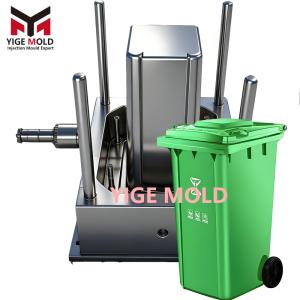
Lid-Mounted Industrial Bin Mold

Lid-Integrated Industrial Trash Bin Mold
Product Definition:
A lid-integrated industrial trash bin mold is a specialized injection molding tool system designed for manufacturing industrial-grade trash bins. Its core feature is that the lid is structurally connected or pre-assembled with the bin body directly within the mold, via hinges, pivots, or a unified structure. The final product is typically a complete functional unit with a permanently or semi-permanently attached lid, widely used in manufacturing plants, warehousing and logistics facilities, and outdoor industrial sites. Key performance requirements include ultra-high hinge durability, reliable sealing, vandal resistance, and compatibility with automated handling equipment.
Mold Technology System:
-
Integrated Cavity Design for Lid and Body
-
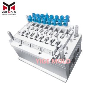
Family Mold Configuration: A single mold base typically integrates independently designed but coordinated bin body cavities and lid cavities, enabling the simultaneous molding of both components in a single injection cycle. This ensures material consistency and color matching.
-
In-Mold Hinge Formation Technology: High-end molds incorporate mechanisms to directly form living hinges (for PP) or pivot pin sockets between the lid and a flange on the bin body in a single shot, eliminating secondary assembly. This requires precise thermal management of the hinge area to prevent weak points.
-
Post-Molding Assembly Integration Design: Some mold designs create interlocking features on separate lid and body parts. These parts can be quickly assembled automatically or manually after ejection, with the assembly precision ensured by the mold structure.
-
-
Complex Action Mechanisms
-
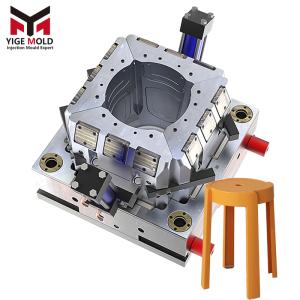
Retractable Angled Lifters and Angular Slides: To form undercuts on the interior of the bin body or lid, such as hinge holes, latch receptacles, and gas spring mounting points, the mold employs a system of retractable angled lifters and hydraulically actuated angular slides. These components must retract completely to allow clean demolding.
-
Sequential Valve Gate Control: For complex lid features like ribs and handle recesses, a hot runner system with sequential valve gate control is used. By controlling the gate opening sequence, the lid details are filled first, pushing weld lines to non-critical areas before filling the main body, ensuring structural strength and surface quality.
-
-
Enhanced Cooling for Large, Flat Areas
-
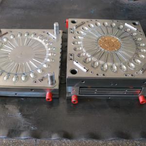
The lid, being a large, flat, or slightly curved component, is prone to warpage. Its cavity employs conformal cooling channels (via 3D-printed inserts) or baffle cooling circuits to maintain a near-isothermal surface temperature, which is critical for dimensional stability.
-
The bin body cavity, especially around hinge mounting areas, uses high thermal conductivity copper alloy inserts to rapidly extract heat from these thick sections, preventing sink marks and reducing cycle time.
-
-
Ejection and Automated Handling System
-
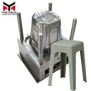
Considering the product's large size and the tendency for deep draws to stick, the bin body cavity uses a combination of sleeve ejectors at the bottom and stripper plate ejection around the perimeter. The lid is ejected via a network of low-profile ejector pins placed on non-visible surfaces.
-
Robotic Extraction Integration: The mold design incorporates features (e.g., gripper access points, built-in part breakaway geometry) to facilitate the use of a robotic arm. This allows for the safe removal and positioning of the often-large, pre-assembled lid-body unit or the separation of parts for downstream operations.
-
Manufacturing and Quality Focus:
-
Material: Primarily High Molecular Weight HDPE or Polypropylene Copolymer to ensure impact strength and hinge fatigue life.
-
Dimensional Control: Key aspects are the alignment accuracy of hinge points (tolerance between mating lid and body features typically ≤0.5mm) and the flatness of the lid sealing surface to ensure an effective seal.
-
Functional Testing: During trial runs, it is necessary to verify lid opening/closing clearance, smoothness of operation (tested over thousands of cycles), and the structural integrity of any in-mold assembled hinges.
Application Areas:
Bins produced by such molds are used for:
-
Heavy-Duty Industrial Waste Collection: Used within factories, featuring fixed lids to prevent debris scattering.
-
Recycling Stations: Lids are often color-coded and integrated with the body.
-
Construction Sites: Equipped with sturdy, attached lids to withstand harsh environments and rough handling.
Market Driver:
The demand stems from the need for more durable, lower-maintenance industrial trash bins. Compared to products with loose or easily damaged separate lids, the integrated design offers significant reliability advantages.