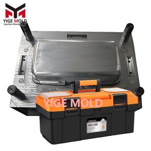
Plastic Pallet Tooling

 Professional Manufacturing Technology Analysis of Plastic Pallet Tooling
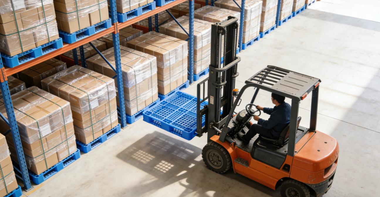
Preface: Precision Equipment Supporting Modern Logistics Systems
In today's highly developed global supply chains and automated warehousing systems, plastic pallets, as the core of unitized logistics carriers, directly determine logistics efficiency, cargo safety, and operational costs. The key element dictating the quality, performance, and production efficiency of plastic pallets is the plastic pallet tooling behind them. This technical analysis aims to systematically explain the design philosophy, manufacturing processes, and core value of professional plastic pallet tooling, demonstrating how precision engineering transforms high-performance polymer materials into reliable and efficient logistics equipment.
Chapter 1: Design Philosophy Centered on Structural Mechanics
Excellent tooling design begins with a deep understanding of the product's end-use scenarios and scientific structural optimization. The design of plastic pallet tooling is far more than a simple cavity copy; it is a comprehensive consideration of mechanics, materials science, and manufacturing processes.
1.1 Topology Optimization of the Load-Bearing System
We utilize Computer-Aided Engineering (CAE) and Finite Element Analysis (FEA) software to simulate extreme load conditions (such as concentrated loads, uniformly distributed loads, and dynamic impact loads) on the pallet in a virtual environment. Based on simulation data, topology optimization is performed on the layout of feet, the direction and cross-sectional shape of reinforcing ribs, and the grid structure of the deck. The goal is to achieve optimal material distribution, balancing lightweight design with high strength, while ensuring performance metrics for static load (typically ≥6 tons) and dynamic load (typically ≥1.5 tons). For example, the roots of feet in a nine-leg pallet are designed with a gradually thickening profile to disperse stress; reinforcing ribs in a grid-style bottom plate adopt wavy or arched structures to enhance bending stiffness.
1.2 Pre-integration of Functional Details
End-user requirements must be "prefabricated" into the structure during the tooling design phase:
-
Anti-slip System: The top deck surface is not perfectly smooth. Instead, regular patterns of dots, stripes, or grids are created through mold etching or precision machining to increase the coefficient of friction and prevent cargo slippage.
-
Handling Friendliness: Guide ramps are designed at the entrances of forklift pockets for easier fork entry; reinforcing ribs are designed in non-supporting areas of the bottom to prevent damage from improper forklift handling.
-
Stacking and Nesting Stability: For stackable pallets, the tooling must precisely control the draft angle of sidewalls and the fit tolerances of reinforcing ribs. For nestable pallets, nesting guide structures and load-bearing limit stops must be carefully designed to ensure stable and easy separation.
1.3 Runner Design for Manufacturability and Efficiency
Addressing the large projected area and long flow paths characteristic of pallets, tooling employs a Sequentially Valve-Gated Hot Runner System. By timing the opening of multiple hot nozzles, the melt front is guided along an optimized path to fill the cavity, effectively eliminating weld lines caused by long flow paths and reducing injection pressure. The design of the cooling system is even more critical. We use 3D Conformal Cooling Channels to ensure uniform and efficient cooling in thick-walled areas like feet and reinforcing ribs. This is the decisive factor in shortening the cycle time (optimizable to 70-90 seconds) and controlling product warpage.
Chapter 2: Precision Engineering Practices for High-Reliability Manufacturing
The design blueprint requires top-tier manufacturing processes to realize. The reliability, lifespan, and accuracy of the tooling directly determine production line stability and product consistency.
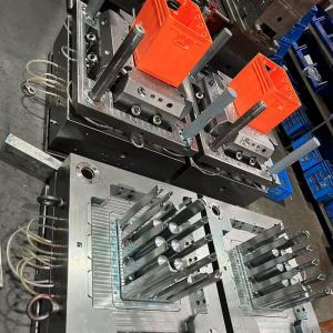
2.1 Heavy-Duty Frame and Precision Cavity Machining
Pallet tooling is massive in size (often exceeding 2.5 meters). The tooling base utilizes pre-hardened premium steel (e.g., P20/718), validated for rigidity via FEA to ensure no deformation under long-term, high-tonnage (typically 800-2000 ton injection molding machine) clamping force. Cavity machining is the core process:
-
Large Gantry 5-Axis Machining Centers are used to complete high-precision milling of complex surfaces in a single setup, ensuring symmetry and dimensional accuracy of foot and rib positions.
-
For deep cavities, narrow slots, and other hard-to-reach areas, Precision Slow Wire EDM and Deep Cavity EDM processes are employed to guarantee clean corners and surface quality.
-
All fitting surfaces and slider guides undergo Ultra-Precision Grinding and receive special surface treatments (such as chrome plating or nitriding) to enhance wear resistance, reduce the coefficient of friction, and ensure smooth operation even after hundreds of thousands of cycles.
2.2 Reinforced Design of Core Movement Systems
The complex structure of pallets necessitates equally complex tooling movement mechanisms:
-
Large Angled Lifts and Internal Core Pulls: Used to form the intricate reinforcing ribs and undercuts on the pallet bottom. These mechanisms are manufactured from high-toughness alloy steel and are designed with self-lubricating bearings and forced cooling channels to withstand high-frequency, high-load reciprocating motion.
-
Synchronization of Multiple Ejection Systems: To ensure smooth demolding of large parts, the tooling is equipped with dozens or even hundreds of ejector pins, assisted by hydraulic cylinders or nitrogen springs to achieve synchronized, stable, and balanced ejection force, preventing ejection marks or part distortion.
2.3 Full-Process Quality Control and Verification
Quality control runs through the entire process, from ultrasonic testing of incoming steel to CMM inspection of critical components, and finally to checking the tooling clamping clearance after final assembly (controlled within 0.02mm). Trial Run Validation before tooling delivery is the final and most crucial step. We operate the tooling continuously for 72-120 hours under simulated mass production conditions, systematically testing its performance across different process parameters. Hundreds of samples are produced for comprehensive dimensional, load-bearing, and drop tests. The tooling is only released after all data meets the standards.
Chapter 3: Deep Synergy Between Materials Science and Process Adaptation
The tooling must be optimized for specific material processes. We adjust tooling design based on the properties of different plastics.
3.1 Optimization for HDPE (High-Density Polyethylene)
HDPE is the most common pallet material, offering good toughness and impact resistance, but with relatively high shrinkage. Therefore, special attention is paid to the tooling's cooling system to control uniform shrinkage, and the ejection system is reinforced to overcome its higher in-mold holding force.
3.2 Optimization for PP (Polypropylene)
PP offers better rigidity, often used where higher flexural modulus is required. Its flow characteristics differ from HDPE, necessitating adjustments to the tooling's hot runner system and gate sizes. Its potentially more pronounced warpage tendency is compensated for through cooling system design.
3.3 Adaptation for Reinforced/Modified Materials
For modified materials containing glass fibers or minerals, the tooling must account for their higher abrasiveness. Cavity and runner surfaces require higher hardness steel or special coatings, and the fit clearances of moving parts need fine-tuning to accommodate abrasive particles.
Chapter 4: Value Delivery – From Technical Solution to Stable Mass Production
We deliver not just tooling, but a manufacturable solution.
-
Technical Alignment Phase: Based on customer-provided pallet usage conditions (loads, environment, automation equipment interfaces, etc.) and material selection, we provide a preliminary proposal including DFM (Design for Manufacturability) Report and Mold Flow Analysis Report.
-
Manufacturing and Validation Phase: During manufacturing, progress updates and photos are provided at key milestones (e.g., after tooling base completion, after cavity finishing). During the trial run phase, a detailed Trial Run Report is issued, documenting optimal process parameters (temperature, pressure, speed, time curves).
-
Mass Production Support Phase: Upon tooling delivery, a complete Maintenance Manual and Wear Parts List are provided. Our engineers can offer on-site debugging support to ensure the tooling reaches a stable state quickly on the customer's production line.
Conclusion
Plastic pallet tooling is a comprehensive precision engineering project in modern industry and logistics. It integrates structural mechanics design, polymer materials science, precision mechanical machining, and automation control technology. Its ultimate goal is to create an industrial tool capable of efficiently, stably, and durably producing hundreds of thousands of high-quality, highly consistent plastic pallets. We remain steadfastly focused on this core mission, applying professional expertise and rigorous craftsmanship to build solid and reliable manufacturing cornerstones for our clients, jointly supporting the efficient operation of the modern logistics world.