Plastic Planter Mold

Comprehensive Technical Analysis of Plastic Planter Mold
I. Product Classification and Mold Positioning
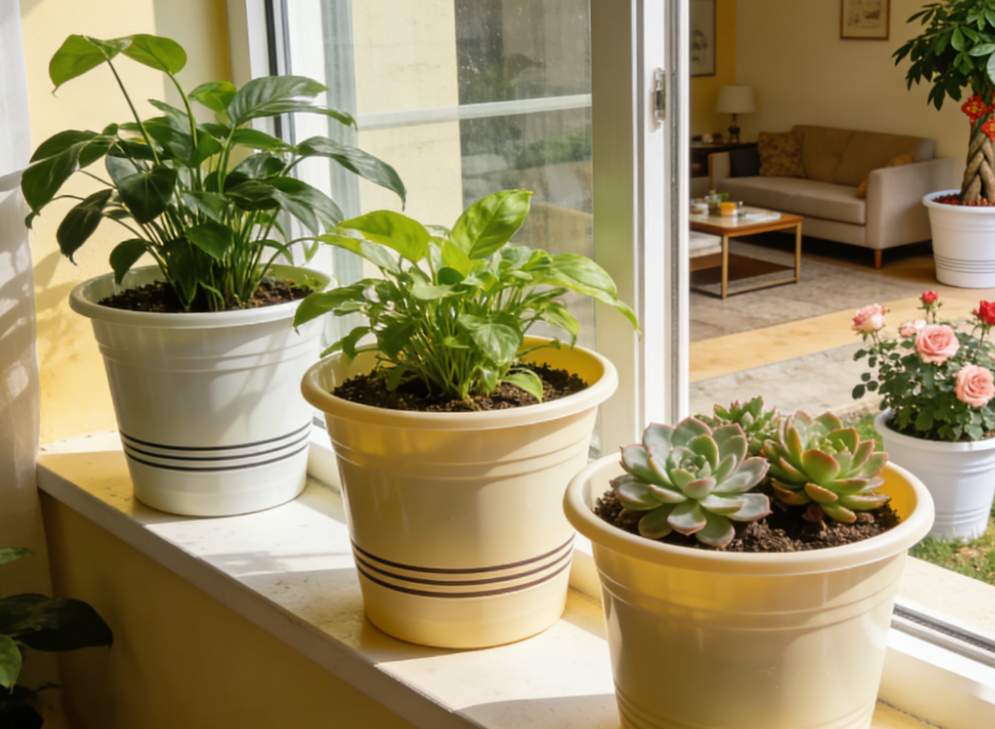
Plastic planters are categorized by usage scenario:
-
Indoor decorative pots (wall thickness 1.2-1.8mm, emphasis on surface texture)
-
Outdoor planting pots (wall thickness 2.5-4.0mm, emphasis on structural strength)
-
Hanging planters (with hanging structure, requiring special gating design)
Molds must meet the following core specifications:
-
Product weight deviation ≤ ±2%
-
Draft angle 0.5°-1.5° (slightly increased in textured areas)
-
Bottom drainage hole accuracy ±0.1mm
-
Stacking stability (multi-layer stacking without jamming)
II. Innovative Mold Structure Design
2.1 Irregular Curved Surface Forming System
-
Natural Texture Replication Technology:
-
Bark/stone textures using silicone replication process, texture depth 0.3-0.8mm
-
Gradient texture areas using laser texturing + chemical etching composite process
-
Texture compensation coefficient set (shrinkage rate 1.2-1.8 times)
-
-
Bottom Ventilation Structure:
-
Movable inserts for forming ventilation holes (diameter 3-8mm)
-
Combined angled lifter + sleeve ejection mechanism for simultaneous hole demolding
-
Ventilation hole draft angle designed at 3-5°
-
2.2 Double-Layer Cooling System
|
Cooling Area |
Water Channel Form |
Water Temperature Control |
Effect Requirements |
|---|---|---|---|
|
Pot Body Surface |
3D Conformal Channels |
15-20°C |
Temperature difference ≤3°C |
|
Bottom Thick Wall |
Jet-Type Channels |
10-15°C |
Eliminate sink marks |
|
Edge Thin Wall |
Spiral Channels |
20-25°C |
Prevent premature freezing |
2.3 Self-Resetting Ejection Mechanism
-
Multi-Stage Ejection Design:
-
First stage: Stripper plate ejection at pot rim (stroke 5-8mm)
-
Second stage: Air-assisted ejection at pot bottom center (pressure 0.3-0.5MPa)
-
Third stage: Sidewall spring block demolding (customized spring force calculation)
-
-
Anti-Sticking Measures:
-
Nitrogen springs for ejection assistance in deep cavity areas
-
Teflon coating on ejector pin surfaces
-
Automatic mold release spray system (every 30 cycles)
-
III. Material and Surface Treatment Solutions
3.1 Mold Steel Configuration
┌────────────────┬──────────────┬─────────────┐
│ Component      │ Material     │ Treatment   │
├────────────────┼──────────────┼─────────────┤
│ Cavity Body    │ P20 Pre-hard │ Pre-hard+Nitriding │
│ Texture Inserts│ 718H         │ Mirror Polishing  │
│ Moving Parts   │ 718H         │ Hardening+Hard Chrome │
│ Hot Runner System│ 718H       │ Oxidation Treatment │
└────────────────┴──────────────┴─────────────┘
Steel Selection Notes:
-
P20 Pre-hard Steel: Hardness HRC 29-33, suitable for cavity bodies, offering good machinability and cost advantages
-
718H Steel: Hardness HRC 33-38, used for texture inserts, moving parts, and hot runner systems, providing higher wear resistance and thermal stability
3.2 Surface Treatment Technology
-
Texture Durability Treatment:
-
High-gloss areas: Electrolytic polishing to Ra ≤ 0.025μm
-
Matte areas: Sandblasting treatment (180-240 grit)
-
Special textures: Nano PVD coating (thickness 2-5μm)
-
-
Anti-Corrosion Treatment:
-
Coastal areas: Electroless nickel plating (thickness 15-20μm)
-
High humidity environments: DLC diamond-like coating
-
General solution: Zinc-nickel alloy plating
-
IV. Key Molding Process Technologies
4.1 Multi-Stage Injection Process
Injection Stage Control:
Stage 1: 25% flow filling bottom → Pressure 40-60MPa
Stage 2: 50% flow filling main body → Pressure 60-80MPa
Stage 3: 25% flow packing → Pressure 30-40MPa
Stage 4: Gas-assist (optional) → Pressure 8-12MPa
4.2 Deformation Control Strategy
-
Pre-Deformation Compensation:
-
Pot rim ovality compensation 0.3-0.5%
-
Pot bottom flatness reverse deformation 0.2-0.3mm
-
Sidewall curvature correction factor 1.05-1.08
-
-
Precise Mold Temperature Control:
-
Front mold: 60-65°C (ensuring appearance)
-
Rear mold: 45-50°C (controlling shrinkage)
-
Local heating: Texture areas +5-8°C
-
V. Special Process Equipment
5.1 Quick Color Change System
-
Two-color planters using rotary mold structure
-
Color change time ≤15 minutes (traditional process requires 2 hours)
-
Residual color difference ΔE ≤0.8
5.2 Intelligent Monitoring Devices
-
Vision Inspection System:
-
Detects texture integrity (5MP camera resolution)
-
Identifies short shots/flash defects (recognition rate ≥99.5%)
-
Automatically sorts defective products
-
-
Pressure Monitoring System:
-
Cavity pressure sensors (accuracy ±0.2MPa)
-
Ejection pressure monitoring (prevention of ejection marks)
-
Real-time data upload to MES system
-
VI. Mold Manufacturing Precision Control
6.1 Machining Process Flow
Rough Machining → Heat Treatment → Semi-Finish → Texture Machining → Finish → Assembly/Debugging
  │               │               │              │               │          │
1mm allowance   Hardness       0.2mm         Depth         Ra≤0.4μm  Clearance
                control        allowance     control                  inspection
6.2 Critical Dimension Control
-
Pot rim diameter tolerance: ±0.15% (max ±0.3mm)
-
Pot body roundness error: ≤0.2% of diameter
-
Drainage hole position tolerance: ±0.1mm
-
Stacking fit clearance: 0.3-0.5mm
VII. Quality Control System
7.1 Process Inspection Items
|
Inspection Time |
Inspection Item |
Standard Requirement |
Inspection Tool |
|---|---|---|---|
|
First Shot after Startup |
Weight/Dimensions |
Weight ±2%, Dimensions ±0.3% |
Electronic Scale/Calipers |
|
Every 2 Hours |
Appearance/Texture |
Clear texture without defects |
Magnifier/Comparison Template |
|
Each Shift |
Stacking Test |
5-layer free stacking without jamming |
Stacking Test Fixture |
|
Daily |
Pressure Curve |
Deviation from standard curve ≤5% |
Pressure Sensor |
7.2 Product Performance Testing
-
Drop Test: Free fall from 1m height (3 times each on bottom and sides)
-
Weather Resistance Test: UV irradiation 500 hours, color difference ΔE ≤2.5
-
Load Test: Fully loaded with soil (simulating usage) hung for 7 days
-
Freeze-Thaw Test: -20°C to +60°C cycling 20 times without cracking
VIII. Maintenance Specifications
8.1 Daily Maintenance Checklist
┌──────────────┬─────────────┬─────────────┐
│ Item         │ Frequency   │ Standard    │
├──────────────┼─────────────┼─────────────┤
│ Parting Surface│ Each Shift │ No material debris/oil │
│ Guide Lubrication │ Daily   │ Adequate grease │
│ Ejection System│ Weekly    │ No abnormal noise/jamming │
│ Water Channel │ Monthly    │ Flow reduction ≤10% │
│ Texture Area  │ Every 30k cycles │ Texture clarity ≥95% │
└──────────────┴─────────────┴─────────────┘
8.2 Overhaul Technical Standards
-
100k cycles: Replace all seals, inspect hot runner heaters
-
300k cycles: Repair texture areas, re-polish
-
500k cycles: Complete dimensional inspection, evaluate refurbishment value
IX. Cost Optimization Measures
9.1 Material Saving Solutions
-
Runner volume optimization reduces scrap rate from 15% to 8%
-
Variable wall thickness design reduces average weight by 12-15%
-
Recycled material usage up to 30% (without affecting appearance)
9.2 Energy Consumption Control
-
Variable frequency pump controls cooling water flow
-
Hot runner zone temperature control reduces power consumption by 18%
-
Quick mold change system reduces standby energy consumption
X. Application Case Data
10.1 Typical Mold Parameters
-
Mold dimensions: 800×600×450mm
-
Number of cavities: 1×2 (symmetrical layout)
-
Total weight: 4.2 tons
-
Molding cycle: 35-45 seconds
-
Daily production capacity: 15,000-20,000 pieces (three-shift system)
-
Mold life: ≥800,000 cycles
10.2 Economic Benefit Analysis
|
Item |
Traditional Mold |
Optimized Mold |
Improvement |
|---|---|---|---|
|
Molding Cycle |
55 seconds |
38 seconds |
↓31% |
|
Scrap Rate |
12% |
6.5% |
↓46% |
|
Energy Consumption |
18 kWh/t |
14 kWh/t |
↓22% |
|
Maintenance Frequency |
1500 cycles/time |
5000 cycles/time |
↓70% |
Conclusion
Plastic planter molds using the P20 and 718H steel combination achieve cost optimization while ensuring performance. The technical core lies in addressing three major challenges: complex texture replication, thin-wall deformation prevention, and efficient demolding. Through reasonable material selection, innovative structural design, and precise process control, modern molds can achieve:
-
Texture replication accuracy ≥95%
-
Product qualification rate ≥98.5%
-
Mold service life extended by 30%
-
Comprehensive production cost reduced by 25%
It is recommended that users select mold configurations based on actual production needs and establish a comprehensive preventive maintenance system to fully utilize mold performance and achieve optimal economic benefits.