Plastic Tool Case Mold

Plastic Tool Case Mold: The Industrial Guardian of Structural Integrity and the Precision Forging of Protection
In the rugged ecosystem of industrial and household storage, the plastic tool case stands as a silent guardian, shielding precision instruments and heavy-duty implements from the chaos of the external world. It is the armor of the workshop, the fortress of the repairman, and the first line of defense against impact, dust, and moisture. However, transforming a simple sheet of plastic into a robust, impact-resistant vessel capable of withstanding the rigors of a job site requires a manufacturing system defined by strength and precision—the Plastic Tool Case Mold. It is not merely a shaper of polypropylene or ABS but a precision forging system that encodes the logic of protection into every cubic millimeter of the product. From the seamless flow of integral hinges to the intricate locking of internal compartments, this mold is the unsung hero of industrial organization, casting durability into form.
The Architecture of Impact Resistance: Forging the Shield
The primary mandate of a tool case is survival—surviving drops, kicks, and the crushing weight of other equipment. This demands that the mold be engineered not just for shape, but for structural resilience. The mold design must orchestrate the flow of high-toughness materials like PP or ABS to ensure uniform wall thickness, eliminating weak points where stress could concentrate and cause fracture.
Engineers utilize advanced Moldflow analysis to predict the behavior of the polymer melt, optimizing gate locations and runner systems to align the molecular orientation with the direction of expected impact. This "molecular forging" ensures that the final product possesses isotropic strength, meaning it is equally tough in every direction. The cooling system within the mold is designed to minimize residual stress, preventing warping that could compromise the seal. In this way, the mold acts as a metallurgist of plastics, transforming raw resin into a high-performance shield that absorbs kinetic energy rather than shattering under it.
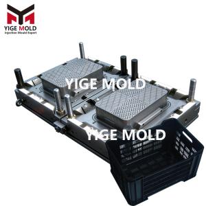
The Mechanics of Complexity: Sliders, Lifters, and the Internal Labyrinth
A modern tool case is far more than a hollow box; it is a complex organizational system. Internal ribs for stacking strength, slots for latches, and compartments for custom foam inserts require a mold capable of executing a complex mechanical ballet. This is where the mold's "internal anatomy"—the sliders and lifters—comes into play.
To form the undercuts required for sturdy latches or side handles, the mold employs high-precision hydraulic or mechanical sliders that move laterally to release the product without damage. For the intricate internal grid structures that hold tools in place, a series of lifters rise and retract in perfect synchronization with the ejection system. These components must operate with micron-level timing; a fraction of a second out of sync could result in a collision that damages the mold or a "flash" defect that ruins the case's seal. This precise coordination allows the tool case to feature complex, user-friendly geometries while maintaining a smooth, snag-free exterior.
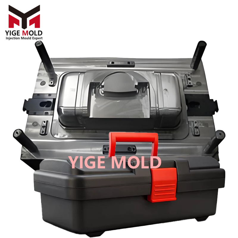
The Miracle of the Integral Hinge: The Fatigue-Defying Connection
One of the most challenging feats in tool case molding is the creation of the "integral hinge" or "living hinge"—the thin strip of plastic that connects the lid to the base, allowing it to open and close thousands of times without breaking. This requires a mastery of both material science and ultra-precision machining.
The mold cavity at the hinge area is machined to an incredibly thin tolerance, often just a fraction of a millimeter. This demands that the plastic melt flows rapidly and seamlessly across this gap, fusing the two halves into a single, continuous piece. The steel used in this area must be polished to a mirror finish to prevent any flow hesitation that could lead to weak spots. Furthermore, the mold design must account for the "shrinkage" of the plastic as it cools, ensuring the hinge curls naturally without cracking. This engineering marvel transforms a potential point of failure into a durable, flexible joint, embodying the principle of "form follows function" in its purest sense.
Conclusion
The plastic tool case mold is the silent architect of industrial durability. Through the architectural design of impact resistance, it forges a shield against the elements; through the complex mechanics of sliders and lifters, it creates order out of chaos; and through the miracle of the integral hinge, it defies the fatigue of repetition. Behind every rugged tool case lies a mold that has mastered the physics of stress, flow, and motion. It does not hold the wrench or the drill, but it creates the sanctuary that keeps them safe. It is the precision forging master of the storage world, silently casting the reliability and strength that professionals depend on every day.