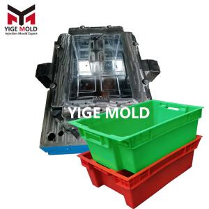
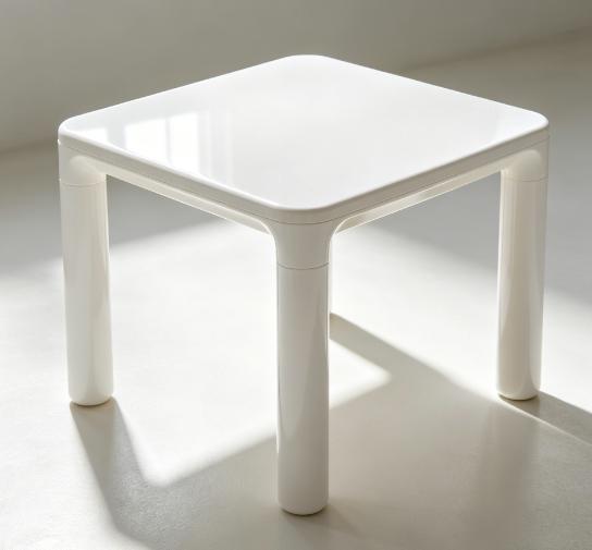
Square plastic table mold


Introduction to Square Plastic Table Molds
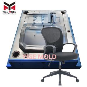
I. Overview of Square Plastic Table Molds
1.1 Definition of Square Plastic Table Molds
Square plastic table molds are specialized plastic forming tools designed for manufacturing square plastic tables. Composed of a fixed mold (cavity side) and a moving mold (core side), they are typically fabricated from high-quality steel through precision machining. The mold contains an internal cavity that matches the exact shape and dimensions of the final table. When plastic raw materials are heated to a molten state and injected into the mold cavity via an injection molding machine, the material cools and solidifies within the mold to form a structurally complete and dimensionally accurate square plastic table. Characterized by compact structure and high precision, these molds ensure stable product quality and excellent surface finish, making them indispensable equipment in the plastic furniture manufacturing industry.
1.2 Application Fields of Square Plastic Table Molds
-
Furniture Manufacturing: Widely used to produce various household and commercial plastic tables, such as dining tables and study desks, meeting diverse furnishing needs.
-
Outdoor Leisure: Leveraging the weather resistance and lightweight properties of the produced tables, these molds are used for manufacturing leisure furniture in parks, plazas, and public spaces, as well as portable tables for camping and picnics.
-
Office Furniture: Providing modern offices with simple yet durable office desks, contributing to a comfortable and efficient working environment.
II. Structure and Characteristics of Square Plastic Table Molds
2.1 Structural Composition
The structure of a square plastic table mold is complex and sophisticated, comprising several key systems:
-
Mold Cavity: The core part that directly determines the shape and size of the table. It consists of the fixed cavity and moving cavity, which close to form the complete square space.
-
Mold Base: Provides support and fixation, including the fixed plate, cavity plate, core plate, and support pillars.
-
Gating System: Guides molten plastic into the cavity, consisting of the sprue (connecting to the machine nozzle), runners (distributing plastic evenly), and gate (entrance to the cavity).
-
Cooling System: Temperature regulation is achieved through internal water channels, ensuring the plastic solidifies at the appropriate temperature.
-
Ejection System: After molding, components like ejector pins push the finished table out of the mold for removal.
These components work in synergy to complete the production cycle.
2.2 Features and Advantages
-
High Precision: Utilizing advanced machining equipment, cavity dimensions are controlled at the micron level, ensuring the final tables are dimensionally accurate and geometrically regular.
-
Durability: Typically constructed from high-quality steel and treated with processes like heat treatment, the molds possess high hardness and wear resistance. They maintain stable performance under long-term high-temperature and high-pressure conditions, resulting in a long service life.
-
Production Efficiency: The rational structure ensures tight coordination between injection, cooling, and ejection processes. Short cycle times, high automation, and reduced labor requirements significantly lower production costs and increase output. The resulting tables feature smooth surfaces requiring minimal post-processing, allowing for immediate use.
III. Manufacturing Process of Square Plastic Table Molds
3.1 Material Selection
Material selection is diverse, with steel being the mainstream choice:
-
Cold Work Die Steels: Such as Cr12MoV and SKD11, known for high hardness and wear resistance. Cr12MoV (hardness up to 58-60 HRC after quenching) is suitable for high-precision, high-wear parts.
-
Pre-hardened Steels: Such as P20, pre-hardened to 30-35 HRC. It offers good machinability and is often used for medium-complexity molds or medium-to-small batch production.
-
Aluminum Alloys: Used for specific applications requiring good thermal conductivity and lightweight properties, though they offer lower strength and wear resistance compared to steel.
Selection depends on usage requirements, production volume, and budget.
3.2 Manufacturing Process Flow
The manufacturing process is rigorous and systematic:
-
Design: Using CAD/CAE technology to design the mold structure based on the table's requirements, followed by mold flow analysis to optimize the design.
-
Rough Machining: Removing excess material from the mold blank via milling and drilling.
-
Heat Treatment: Processes like quenching and tempering are applied to enhance hardness, wear resistance, and toughness.
-
Finish Machining: High-precision CNC machining centers perform milling and grinding to achieve final dimensional accuracy and surface finish.
-
Assembly: Precise assembly of all components (cavity, base, gating, cooling, ejection systems).
-
Trial Run (T0): Installing the mold on an injection machine for test production. Adjustments and repairs are made based on trial results until the mold consistently produces qualified square plastic tables.
IV. Market Status and Trends of Square Plastic Table Molds
4.1 Market Status Analysis
The market is currently experiencing vigorous growth. Driven by the expansion of the plastic furniture industry, demand for these molds continues to rise. Market data indicates sustained growth and a stable upward trend.
The competitive landscape is intense, populated by numerous manufacturers:
-
Large Enterprises: Possess strong technical capabilities and advanced equipment, capturing high market share through high-quality molds and premium services.
-
SMEs: Survive through flexible production models and competitive pricing.
Consumer demand for enhanced aesthetics and functionality in plastic tables has pushed mold manufacturers to continuously innovate in terms of precision and performance to adapt to market changes.
V. Usage and Maintenance of Square Plastic Table Molds
5.1 Usage Methods and Precautions
-
Installation: Ensure compatibility with the injection molding machine. Align the mold's locating ring with the machine's positioning hole.
-
Preheating: Preheat the mold to 80-120°C before injection to prevent internal stress caused by rapid cooling.
-
Parameters: Set injection pressure (typically 70-100 MPa), temperature, and speed according to the raw material specifications.
-
Monitoring: Regularly inspect for abnormal noises, leaks, or other issues during production.
-
Cleaning: Clean the cavity and runners immediately after production to prevent residual plastic from hardening.
5.2 Maintenance Measures
To extend mold life, routine maintenance is essential:
-
Cleaning: Thoroughly clean the cavity and mold base after each production run to remove plastic residue and debris.
-
Inspection: Check for wear or deformation in components like ejector pins and sliders; repair any issues promptly.
-
Lubrication: Regularly lubricate moving parts (guide pillars, guide bushings) with appropriate oil to reduce friction.
-
Rust Prevention: Apply anti-rust oil to the surface, especially if stored in humid environments.
-
Cooling System Check: Periodically ensure water channels are clear of blockages and leaks to maintain proper thermal regulation.