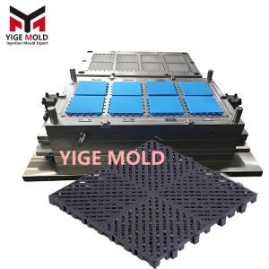
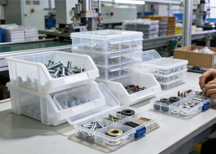
Parts Box Mold

 In-depth Analysis of Parts Box Mold Design and Manufacturing Technology
I. Product Function and Mold Positioning
Parts boxes serve as standardized containers in industrial storage, automotive repair, electronic assembly, and other fields. Their molds must meet the following core requirements:
-
Multi-layer stacking stability (8 layers without tilting)
-
Modular combination compatibility (multiple sizes interconnectable)
-
High strength and impact resistance (no cracking when dropped from 1.5m)
-
Precision dimensional tolerances (internal compartment size deviation ≤±0.3%)
II. Innovative Mold Structure Design
2.1 Multi-Cavity Modular Layout
-
Symmetrical layout of 1×2 to 1×4 cavities, with cavity spacing optimized via dynamics analysis
-
Independent cooling systems for each cavity, temperature difference controlled within ±2°C
-
Central hot runner to cold runner system for automatic gate separation
2.2 Precision Partition System
-
Movable Partition Mechanism:
-
Hydraulically driven T-sliders for forming partition thicknesses of 1.5-2.0mm
-
Early return device ensures partition core-pulling accuracy of ±0.02mm
-
0.5° draft angle on partition surfaces to prevent sticking
-
-
Snap-fit Linkage System:
-
Gear-synchronized core pulling for corner snap-fits
-
Undercut depth of 3-5mm, demolding angle of 12-15°
-
Secondary ejection mechanism ensures complete snap-fit demolding
-
2.3 Stacking Structure Molding
-
Combined angled lifter and slider structure for top load-bearing ribs
-
Delayed ejection for bottom anti-slip ribs
-
Stacking guide pins formed via inserts, perpendicularity ≤0.1mm/100mm
III. Materials and Heat Treatment
3.1 Steel Configuration Plan
|
Component |
Main Material |
Hardness |
Special Treatment |
|---|---|---|---|
|
Cavity Body |
P20 |
HRC 30-33 |
Nitriding (depth 0.15mm) |
|
Partition Sliders |
718H |
HRC 34-38 |
Hard chrome plating (0.01mm) |
|
Ejection System |
2316 |
HRC 28-32 |
Phosphating |
|
Guide Components |
Tungsten Carbide |
HRA 90 |
Diamond coating |
3.2 Critical Area Reinforcement
-
718H inserts for snap-fit areas, thickness 20mm
-
Hardened steel strips on parting surface, hardness HRC 52-55
-
Beryllium copper alloy hot runner nozzles, thermal conductivity ≥105W/m·K
IV. Molding Process Control
4.1 Process Parameter Optimization
-
Temperature Control: Front mold 60-65°C, rear mold 40-45°C, material temperature 200-230°C
-
Pressure Curve: Injection pressure 90-120MPa, staged packing control
-
Speed Segmentation: Low-speed filling for partitions (50mm/s) → high-speed filling for main body (350mm/s)
-
Cycle Control: Injection 8s + Cooling 20s + Ejection 3s
4.2 Defect Control Strategy
-
Partition Warpage:
-
Asymmetric cooling: inner cavity temperature 5-8°C higher than outer walls
-
Shaping fixtures applied post-demolding, holding for 2 minutes
-
Triangular reinforcing ribs added to partition roots
-
-
Uneven Stacking Clearance:
-
Gate position optimized via mold flow analysis
-
Top rib areas extended packing time by 30%
-
Three-point positioning ejection, ejection balance ≥95%
-
V. Surface Treatment Technology
5.1 Functional Texture Processing
-
Anti-slip grid etched on inner surfaces (depth 0.3mm, spacing 5mm)
-
Matte finish on exterior walls (Ra 1.2-1.8μm)
-
Laser engraving for identification areas (depth 0.2mm)
5.2 Dimension Marking Technology
-
In-mold numbered inserts for capacity marking
-
Variable date stamps for automatic batch updates
-
Color-coded inserts for visual management
VI. Precision Manufacturing Technology
6.1 Machining Process Control
-
Cavity Machining:
-
Rough machining allowance 0.5mm, using φ20mm tools
-
Semi-finish allowance 0.15mm, ball-end mills R5
-
Finish machining stepover 0.1mm, surface roughness Ra≤0.6μm
-
-
Partition Slider Machining:
-
Slow wire EDM, accuracy ±0.005mm
-
Guide surface grinding, flatness 0.005mm
-
Fit clearance 0.01-0.02mm
-
6.2 Inspection and Acceptance
-
CMM measurement of critical dimensions, tolerance ±0.02mm
-
Blue light scanning of partition positions, deviation ≤0.1mm
-
Trial production of 100 pieces, dimensional stability CPK≥1.33
VII. Mold Maintenance System
7.1 Preventive Maintenance
-
Daily: Clean parting surfaces, check lubrication system
-
Weekly: Measure wear on guide components
-
Monthly: Inspect hot runner system seals
-
Quarterly: Full dimensional accuracy inspection
7.2 Repair Technical Standards
-
Wear Repair:
-
Minor scratches: Polish with diamond paste
-
Moderate wear: Repair via brush plating, coating thickness 0.02-0.05mm
-
Severe damage: Replace inserts
-
-
Dimensional Compensation:
-
Regular cavity dimension measurement, establish wear curves
-
Assess repair necessity every 100,000 cycles
-
Maximum repairs not exceeding 3 times
-
VIII. Quality Control Standards
8.1 Product Performance Indicators
-
Stacking test: 8 layers fully loaded (200kg) for 24 hours without deformation
-
Drop test: 1.5m height drops, 3 times each on corners, edges, and faces
-
Environmental test: -30°C to +70°C thermal cycling
-
Life test: 5,000 open/close cycles, snap-fits remain functional
8.2 Process Control Parameters
-
Product weight deviation: ±1.5%
-
Partition thickness uniformity: ±0.1mm
-
Snap-fit engagement force: 20-40N
-
Color consistency: ΔE≤1.5
IX. Production Efficiency Optimization
9.1 Quick Mold Change System
-
European standard interfaces, mold change time ≤8 minutes
-
Hot runner quick connectors, replacement time ≤2 minutes
-
Pre-assembled ejection system reduces adjustment time
9.2 Automated Production
-
Robotic part removal reduces cycle time by 15%
-
Online vision inspection, automatic rejection of defective parts
-
Automatic mold release spray system, activates every 50 cycles
X. Technical Economic Analysis
10.1 Cost Control Achievements
-
Material utilization rate: 92% (via runner optimization)
-
Mold life: ≥1.2 million cycles
-
Maintenance cost: ≤0.05 CNY/part
-
Energy consumption: 0.8 kWh/kg product
10.2 Production Data Example
-
Mold dimensions: 850×650×500mm
-
Molding cycle: 31 seconds
-
Daily output: 23,000 pieces (three-shift system)
-
Qualification rate: 99.5%
-
Investment payback period: 8 months
Conclusion
Parts box molds represent a typical example of precision multi-functional injection molds. Their technical core lies in solving complex issues such as thin-wall partition molding, multi-directional core-pulling coordination, and stacking precision control. By adopting a combined material solution of P20 and 718H, along with optimized mold structures and strict process control, high precision, high efficiency, and long service life production goals can be achieved. It is recommended to establish a full lifecycle management system for molds in actual production, maximizing mold performance through preventive maintenance and precise repairs, thereby providing reliable support for industrial production.