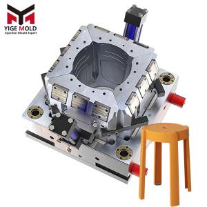
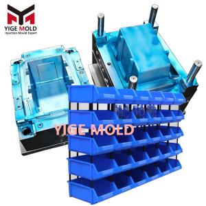
Airtight Container Mold

Airtight Container Mold: A Precision Injection Molding System Based on the Realization of Airtight Functionality
The Airtight Container Mold is a specialized tooling system in the field of plastic injection molding, oriented towards achieving specific functional objectives. Its core design and manufacturing principle lies in producing plastic container components with reliable airtight isolation performance through precise mechanical structures. This system must not only meet the structural requirements of conventional injection molds but also necessitate collaborative design and precision manufacturing across multiple physical fields specifically for the realization of the sealing function.
I. Functional Architecture: Forming Realization Pathways for Airtight Mechanisms
The mold's structural design is entirely subservient to the sealing principle of the final product, primarily categorized into the following three realization paths and their corresponding mold solutions:
1. Elastomeric Compression Airtight System
The core feature of such molds is forming precision groove systems on the container body or lid to accommodate O-ring or specially shaped sealing rings. The focal points of mold design include:
-
Tolerance control of the groove cross-sectional geometry, requiring comprehensive consideration of the seal's compression ratio (typically 15-25%) and resilience.
-
Machining quality of groove bottom corners and sidewalls, avoiding stress concentration and installation damage to the seal caused by sharp angles.
-
Flatness control of the corresponding compression surface, ensured through robust mold design and balanced temperature fields to guarantee coplanarity of the mating surfaces on the molded part.
2. Rigid Structural Interlock Airtight System
This solution achieves sealing through interference fit between convex-concave ribs and grooves on the container rim and lid. The main technical challenges for the mold include:
-
Design of the mating dimensions for the interlocking ribs/grooves, requiring precise calculation of material shrinkage to achieve micron-level interference (typically 0.05-0.15mm).
-
Demold feasibility for rib/groove structures with aspect ratios greater than 3:1, often necessitating slider or lifter mechanisms, with strict requirements for draft angle (typically ≥0.5°) and surface finish (Ra ≤ 0.2µm).
-
Ensuring dimensional continuity in the circumferential direction, avoiding parting lines or weld lines in critical sealing areas.
3. Integrated Functional Airtight System
Used for high-end applications like vacuum fresh-keeping containers, the mold must achieve multi-material composite molding or insert molding:
-
Micro-molding of the one-way valve system, involving precision channel formation with diameters less than 1mm.
-
Two-shot or overmolding of rigid plastics with elastomers (e.g., TPE), requiring precise mold alignment systems and zoned temperature control.
-
Precise positioning and overmolding techniques for metal inserts like springs or silicone valve discs.
II. Key Engineering Parameters and Quality Control Dimensions
1. Dimensional Chain Accuracy Control System
-
The mold must establish a dimensional chain centered on the airtight function, focusing on controlling: rim roundness error (≤0.1mm), sealing surface flatness (≤0.05mm), and true position of mating features (≤0.03mm).
-
Utilize mold flow analysis software to predict shrinkage and warpage, applying compensatory adjustments to the mold dimensions, especially for materials with significant anisotropic shrinkage like glass-fiber-reinforced plastics.
2. Optimized Configuration of the Thermal Management System
-
Cooling channel layout adheres to the "conformal cooling" principle, employing densely packed parallel channels or materials with higher thermal conductivity (e.g., beryllium copper inserts) in sealing feature regions.
-
Optimize cooling time via thermal cycle analysis, balancing production efficiency with the reduction of warpage caused by molding residual stress, aiming to control the temperature differential in airtight zones within ±3°C.
3. Application of Surface Engineering Technology
-
Airtight contact areas undergo multi-stage polishing, achieving a mirror finish (Ra ≤ 0.025µm) to reduce the coefficient of friction (potentially below 0.1) and microbial adhesion potential.
-
Mold moving components subject to high-frequency friction (e.g., sliders, lifters) are treated with PVD coatings (e.g., TiAlN) to enhance wear resistance and demolding performance.
III. Collaborative Design Framework Integrating Material, Process, and Mold
1. Mapping Relationship Between Material Properties and Mold Design
-
Design the gating system according to the rheological properties (e.g., shear thinning index) of different polymers, ensuring airtight feature areas fill simultaneously and sufficient packing pressure is established.
-
Design the retention force and fatigue life of snap-fit features based on the material's elastic modulus and creep characteristics, e.g., employing greater interference for PP materials to compensate for stress relaxation.
2. Precise Definition of the Manufacturing Process Window
-
Determine the optimal combination of process parameters, especially the packing pressure profile and cooling time, using Design of Experiments (DOE) methodology to minimize warpage of airtight surfaces caused by differential volumetric shrinkage.
-
Establish data linkage between the mold and injection molding machine for real-time monitoring and compensation of process variations, ensuring dimensional stability between batches (Cpk ≥ 1.67).
IV. System Verification and Reliability Assessment Protocol
1. Function-Based Testing and Verification System
-
Post mold trial, products must pass standardized seal integrity tests such as helium mass spectrometry leak detection (sensitivity up to 10⁻⁸ atm·cc/sec) or negative pressure water immersion testing.
-
Conduct accelerated life testing, simulating actual usage cycles of opening/closing (typically requiring ≥ 10,000 cycles), and verify the attenuation of sealing force.
2. Durability Indicators for the Mold Itself
-
Critical molding components require hardness gradient design (surface hardness HRC 55-60, core maintaining HRC 35-40 for toughness).
-
Predict the mold's fatigue life under long-term alternating loads via Finite Element Analysis (FEA), and implement reinforcement designs in high-stress areas.
Conclusion
The Airtight Container Mold represents an engineering practice paradigm that proceeds from functional requirements, driving the high-level integration of design, material, process, and manufacturing in a reverse manner. It transcends the conventional mold's role as a mere "replication tool," evolving into a complex system requiring the comprehensive use of multidisciplinary knowledge encompassing precision mechanical design, polymer rheology, heat transfer, materials surface science, and statistical process control. Its technical core lies in translating the abstract functional requirement of "maintaining isolation between the internal and external environments" into a series of specific, designable, manufacturable, measurable, and repeatable engineering parameters. A successful Airtight Container Mold is a micro-system engineering project constructed on a millimeter scale. Its ultimate output is not merely a plastic product but a verified airtightness solution with quantifiable reliability metrics. The development in this field will continue to propel various industries—including household food preservation, medical packaging, and precision instrument protection—toward goals of higher reliability and longer-term preservation efficacy.