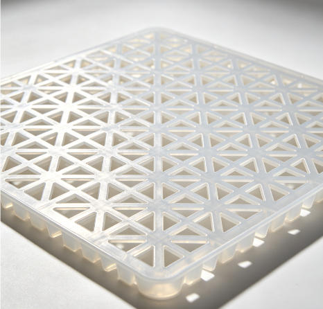
Floor mat injection mould


 Floor Mat Injection Mold: Rheology and Wear-Resistant Structural Design
I. Product Definition and Industry Context
The Floor Mat Injection Mold, technically referred to as a "Polymer Composite Carpet Mold," represents one of the most challenging applications in the injection molding industry, characterized by its large planar area and thin-wall structure. Unlike deep-cavity molds for crates or chairs, the core features of a floor mat mold are its massive projected area (commonly ranging from 500×800 mm to 1000×1500 mm) and extremely low height-to-width ratio. Finished products are primarily used as entrance mats, bathroom anti-slip mats, and All‑Weather Floor Mats (particularly for automotive applications). Materials are predominantly High‑Flow Polypropylene (PP) or Thermoplastic Elastomers (TPE); the latter is increasingly becoming the mainstream choice for high‑end mats due to its rubber‑like touch and excellent resilience.
II. The "Anti‑Warp" Philosophy of Mold Design
Warpage is the mortal enemy of floor mat products. Since flat panels heated on one side cool and shrink unevenly, the primary objective of mold design is thermodynamic balance.
1. Central Radial Gating Layout
To prevent edge curling, side gates are rarely used.
-
Multi‑Point Pin Gate Injection: Molds typically feature 3–4 submarine gates located at the center or diagonal corners. This allows melt flow to radiate outward from the center, counteracting molecular orientation and shrinkage stress.
-
Flow Balance CAE Analysis: During the design phase, Moldflow analysis is mandatory to simulate the path of weld lines. Since visible weld lines are unacceptable on mat surfaces, gates are strategically placed at the roots of the anti‑slip studs on the backside, utilizing a "concealment by function" strategy.
2. Flatness Control of the Parting Surface
The parting surface of a floor mat mold is a vast plane.
-
Relief and Clamping: To prevent damage from foreign particles, a "Relief Step" of 0.02–0.03 mm is designed around the perimeter of the parting surface. Additionally, considering the tie‑bar spacing limitations of injection machines, the thermal expansion coefficient of the mold’s length and width must be precisely calculated, reserving a 0.5–1 mm gap for thermal expansion.
III. Core Manufacturing: Precision Machining of Giants
1. Prestressing Treatment of the Mold Base
-
Material Upgrade: Standard S50C mold bases are prone to "center bowing" under large‑area heating. High‑end floor mat molds utilize Pre‑hardened P20 Steel that has undergone Stress‑Relief Annealing to eliminate internal residual stress, preventing flash thickening caused by frame deformation during operation.
-
Surface Grinding: The top and bottom planes of the mold frame require machining on large‑scale gantry surface grinders, with flatness controlled within 0.02 mm/m². This is the prerequisite for ensuring uniform thickness of the final mat product.
2. Texture Etching (Texturing) on Cavity Surfaces
Functionality is primarily manifested through surface texture.
-
Sandblasting and Chemical Etching: Depending on the application, the cavity surface may receive #60–#120 grit sandblasting (for increased friction) or fine EDM texturing (simulating 3D patterns like cobblestones or cubic grids). This process demands ultra‑low inclusion rates in the mold steel; otherwise, "pinholes" appear after etching.
3. Topology Optimization of Back‑side Ribs
Although the mat appears flat, the back is covered with hemispherical anti‑slip studs and interwoven ribs.
-
High‑Speed CNC Milling: Utilizing high‑feed, shallow‑cut strategies to mill tens of thousands of micro‑studs in a single operation. Programming must pay special attention to "chip evacuation" to prevent micro‑chips from adhering to the cutter head and scratching the cavity.
IV. Thermal Control System: The Challenge of Large‑Area Uniform Temperature
Cooling is notoriously difficult for floor mat molds because heat concentrates across a massive panel.
1. Conformal Cooling Technology
Traditional straight‑drilled holes cannot cover complex contours.
-
3D Printed Inserts: Modern high‑end molds increasingly use SLM Metal 3D Printing to manufacture conformal cooling inserts. Cooling channels run tightly alongside the cavity surface (as close as 5–8 mm) in serpentine or spiral patterns, keeping surface temperature variation within ±2 °C and compressing cooling time from a traditional 60 s to under 30 s.
2. Zoned Independent Temperature Control
-
Multi‑Circuit Design: The mold is designed with 3–4 independent water circuits. The center zone, which retains more heat, is set to a lower water temperature (15–20 °C), while the edges, which cool too quickly, are set higher (40–50 °C). Precise control via temperature controllers induces reverse shrinkage, completely eliminating the chronic problem of edge curl.
V. Ejection and Automation Integration
1. Negative Pressure Relief Design
The contact area between the mat and the core can approach 100%, creating extreme vacuum suction upon mold opening.
-
Air‑Valve Ejector Pins: Micro one‑way valves are embedded within the mold. Upon receiving the mold‑open signal, a solenoid valve injects 0.4 MPa compressed air into the core, forcibly separating the product and preventing tensile deformation.
2. Robotic Part Removal System
Due to their size and tendency to deform, manual removal easily causes creases.
-
Contour Vacuum Gripper Fixtures: Coordinated with injection molding robots, multi‑array vacuum suction cups simulate the motion of human hands supporting the mat, smoothly extracting the product and placing it onto a conveyor belt.
VI. Conclusion
The Floor Mat Injection Mold stands as one of the most extreme categories in the injection molding industry regarding the control of macro and micro scales. It demands the precision of a sculptor in shaping surface textures and the analytical mind of a thermodynamicist to balance temperature fields across square meters. A mature floor mat mold is not merely a tool for plastic forming; it is an industrial artwork representing the perfect fusion of polymer rheology and large‑scale mechanical structure.