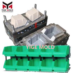
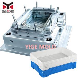
Chicken Cage Crate Mold

Core Technical Focus in Chicken Cage Crate Mold Design and Manufacturing
The Chicken Cage Crate Mold, as a special type of mold for producing thin-walled, high-density lattice/grate structure products, centers its design and manufacturing on achieving a precise balance between structural strength, moldability, and animal safety. The success of the mold hinges on translating a series of interrelated and often conflicting engineering requirements into a physical reality capable of stable production.
I. Mold Design: Addressing the Engineering Challenges of "Fine," "Dense," and "Strong"
The "integrated cage-and-crate" nature of the product presents unique challenges: how to achieve sufficient structural strength in extremely thin grate walls while ensuring perfect filling of the high-density lattice.
-
Runner and Filling Design for Complex Grate Systems
-
Multi-Point Balanced Hot Runner System: Given the large length-to-diameter ratio and high flow resistance of the grates, the mold must employ a multi-point valve-gated hot runner system, injecting simultaneously at several key locations around the grate array. The runner layout must be optimized through precise Mold Flow Analysis to ensure the plastic melt flow fronts reach the end of each grate nearly simultaneously, avoiding weld lines or short shots. Each hot nozzle's temperature must be independently and precisely controllable to address minute differences in fill speed across different zones.
-
Variable Cross-Section Grate and Rib Design: The grate cross-section is not a simple rectangle. The mold cavity is designed to form grates with an "I-beam" or "T-beam" profile, creating tiny reinforcing ribs along the middle or root of the grate. This significantly increases the bending and torsional stiffness of the grates without substantially increasing wall thickness or obstructing the view. This variable cross-section design places extremely high demands on the accuracy of electrode machining and Electrical Discharge Machining (EDM).
-
-
High-Precision, High-Lifetime Slide and Ejection Systems
-
Array of Micro-Precision Slides: To form internal interlocking grates and latch structures, the mold often requires dozens or even hundreds of micro-slides. These slides must operate with absolute synchronization and possess high hardness and wear resistance (typically using cemented carbide or specially surface-treated steel). The fit clearance between slides and cores must be controlled within 0.02-0.03mm to prevent flash while ensuring no seizure at high temperatures.
-
Multi-Point Uniform Ejection Scheme: After cooling and shrinking, the slender grates exert a complex and distributed high holding force on the cores. The mold must be designed with densely and uniformly distributed ejection points, often using a combination of ejector pins, ejector sleeves, and air-assisted ejection. The layout of ejection points must be based on shrinkage simulation analysis to ensure the product is stressed evenly during ejection, preventing grate bending, warping, or "ejector pin blushes."
-
-
Realization of Reinforced Structures and Functional Features
-
Integrated Load-Bearing Frame Molding: The thick-walled perimeter frame and the internal thin-walled grates are molded in one shot, posing a significant challenge for the cooling system. The mold employs differentiated cooling circuits: dense conformal cooling channels are arranged in the thick-walled frame areas for aggressive cooling; cooling in the thin-walled grate areas needs to be relatively gentler to prevent excessive internal stress and grate brittleness caused by overly rapid cooling.
-
Anti-Injury Safety Radii Processing: All safety radii (typically with an R ≥ 1.5mm) at the ends and intersections of the grates must be directly machined into the mold cavity. This requires the use of high-precision 5-axis machining centers or precision EDM technology to ensure smooth radius transitions, free of any machining marks or micro-notches, eliminating injury risks at the source.
-
II. Mold Manufacturing: The Pursuit of Ultimate Precision, Hardness, and Coordination
The manufacturing process is key to translating the complex design into reliable hardware.
-
Precision Machining of High-Hardness Materials
-
Core and cavity components use high-hardness, high-toughness mold steels (e.g., Swedish ASSAB 8407, German 1.2344), hardened to HRC 48-52. Machining deep holes and narrow slots in these hard materials requires high-performance carbide tools and stable high-speed machining strategies.
-
Manufacturing micro-slides is particularly challenging. They are often rough-shaped by Slow Wire EDM (accuracy ±0.003mm) and then finished by precision grinding machines to ensure dimensional and geometric tolerances.
-
-
Manufacturing of Efficient Composite Cooling Systems
-
For the cores and cavities forming the thick-walled frame, 3D Metal Printing (Additive Manufacturing) technology is used to create conformal cooling channels. These channels can perfectly follow the product contour, maintaining a consistent distance from the surface, enabling highly efficient and uniform cooling, significantly reducing cycle time and warpage.
-
Traditionally drilled cooling channels and 3D-printed channels are connected via precisely designed manifolds, ensuring no leakage and balanced flow.
-
-
Stringent Assembly and Debugging
-
The focus of mold assembly is the coordination of hundreds of moving parts. Using a precision mold trial press, the stroke, timing, and locking force of each slide group must be meticulously adjusted with dial indicators to ensure no interference or delay during mold opening and closing.
-
The layout of the vacuum venting system is critical. In areas prone to air traps, such as grate ends and potential weld line locations, precision venting slots with a depth of only 0.01-0.02mm are machined, and a vacuum pump is used for active air evacuation. This removes trapped air, ensuring complete filling at the grate tips and avoiding burn marks or short shots.
-
III. Validation Standards: Testing Beyond the Norm
A successfully trialed mold must pass a series of targeted tests:
-
Short Shot & Pressure Hold Testing: Injection is performed at the extreme limits of the processing window (lower than standard temperature/pressure) to test the mold's filling capability and grate formation integrity under the most adverse conditions.
-
Long-Run Stability Test: Continuous automated production for 50,000 to 100,000 cycles, monitoring dimensional changes of critical grates, wear of the slide system, and stability of the ejection system to ensure the mold's durability for mass production.
-
Functional Safety Test: Finished trial products undergo point-load fatigue testing simulating pecking by bird beaks and body pressure, verifying the grate's long-term impact resistance complies with animal safety standards.
Conclusion: The design and manufacturing of the Chicken Cage Crate Mold is a quintessential case of pushing precision injection molding technology to its limits. It is not merely about manufacturing a product but about solving a chain of interrelated problems—flow, cooling, ejection, and strength—posed by thin-walled, dense structures through top-tier mold engineering. A successful mold is the culmination of runner thermal balance technology, precision slide design, advanced cooling solutions, and high-hardness material machining processes. Its ultimate value is realized in the stable and efficient production of standardized, durable, safe, and reliable management units, providing a solid hardware foundation for the efficient, low-stress operations of modern poultry husbandry.