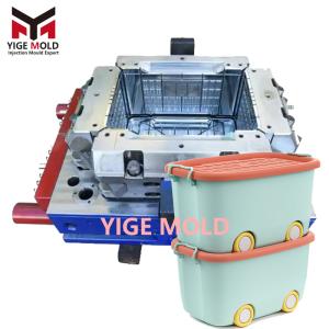
Mop bucket injection mould

Mop Bucket Injection Mold: The Precision Forming Core for Functionally Integrated Plastic Products
Introduction
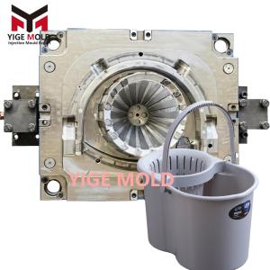
Within the spin mop system, the mop bucket serves not merely as a container but as an integrated platform that combines the four functions of "water extraction," "cleaning," "mobility," and "drainage." Its manufacturing quality directly dictates product performance and service life. The mop bucket injection mold is precisely the critical equipment enabling the efficient, precise, and mass production of this complex plastic component. Its technical substance far exceeds that of standard container molds, involving a deep integration of structural design, rheology, heat transfer, and precision motion control, making it a benchmark product for gauging a mold manufacturer's technical capabilities.
I. Core Contradictions Between Product Functional Requirements and Mold Design
As a functionally integrated, deep-cavity, heteromorphic part, the mop bucket presents multiple challenges for mold design:
-
Integration and Conflict of "Functional Islands": A single bucket body must integrate multiple functional structures, such as the precision bearing structure for the dewatering basket's rotation, the movable lever structure for a foot-operated drain valve, the heavy-duty mounting structure for casters, and an ergonomic handle. These nested "functional islands" within the limited space of the bucket lead to a high density of moving mechanisms inside the mold (sliders, lifters, inserts, etc.), requiring careful design to avoid interference and ensure structural strength.
-
The Mechanical Contradiction of High Aspect Ratio and Thin Walls: The bucket's depth-to-diameter (H/D) ratio often exceeds 1.2, classifying it as a deep-cavity part. Concurrently, to reduce weight and cost, wall thickness is commonly as thin as 1.5-2.0mm. This results in long melt flow paths and high resistance within the mold, while uneven shrinkage during cooling generates internal stress that easily causes irreversible deformation like out-of-roundness, ovality of the opening, or inward collapsing of sidewalls ("buckling"). This imposes extreme demands on the mold's rigidity, cooling uniformity, and gating system design.
-
Challenge of Direct Molding Dynamic Sealing Surfaces: The sealing performance of the drain valve is critical. The mold must directly injection mold the precision mating conical or flat surfaces of the valve body and seat. Their surface finish, profile accuracy, and the fit clearance between them (typically required ≤0.03mm) must be guaranteed entirely by the mold. This places demands on the machining precision (often requiring slow wire EDM or mirror-finish EDM) and wear resistance of the corresponding cavities and cores comparable to those for precision hydraulic components.
-
Unification of Aesthetics and Structural Strength: The bucket's exterior often features complex decorative curves and textures, while the interior is reinforced with a dense network of ribs to withstand water pressure and foot force. The mold must achieve an attractive finish while preventing sink marks and air traps at rib roots. This presents a high demand for the synergistic optimization of gate location, cooling layout, and venting design.
II. Technical Analysis of Core Mold Systems
-
High-Stiffness, Multi-Action Molding System
-
Overall Reinforced Design: Given the large projected area and high injection pressure, mold plates (especially the fixed and moving plates) require increased thickness and employ an integral box-type structure or internal reinforcing ribs to resist elastic deformation under hundreds of tons of clamping force, ensuring parting line sealing and preventing flash.
-
Compound Side-Action Core Pulling: To handle undercuts and recesses in multiple directions around the bucket, a compound solution of "sliders + lifters + hydraulic cylinder direct pull" is commonly used. For example, dewatering basket slots might be formed by collapsible core sliders, foot valve mounting slots by long-stroke, hydraulically actuated sliders, and internal rib undercuts by delay-action lifters. The actuation sequence is controlled by precision limit switches or the injection molding machine program to ensure flawless operation.
-
-
Gating System Targeting Balanced Filling and Low Stress
-
Multi-Point Hot Runner Sequential Injection Molding: A multi-point valve-gated hot runner system is essential. Gates are typically arranged asymmetrically, e.g., with main gates symmetrically placed on both long sides of the bucket, and auxiliary gates at the bucket bottom center or short sides. By programming the sequence and timing of each valve gate's opening, active control of weld line location is achieved, guiding them away from stress-sensitive and visually critical areas like corners and handle roots, and towards concealed locations like ribs.
-
Rheological Optimization of Runners and Gates: Mold flow analysis software is used to simulate and optimize hot runner channel dimensions and gate shapes (commonly fan gates or sub gates), ensuring the melt front advances with balanced speed and temperature, minimizing anisotropic shrinkage caused by molecular orientation differences.
-
-
Ejection and Venting Systems Tailored for Deep-Cavity Characteristics
-
"Air-Assisted + Mechanical" Compound Ejection: Due to the bucket's depth and large surface area, the packing force and vacuum adhesion force against the core are extremely high. In addition to numerous ejector pins and sleeve ejectors, an air ejection system is essential. At the moment of mold opening, compressed air is instantly released through micro-channels in the core, breaking the vacuum and allowing the part to slightly expand away from the core. The mechanical ejection mechanism then follows smoothly, effectively preventing part stretching, ejector pin marks ("blush"), or deformation.
-
3D Venting Network: Venting is not limited to the parting line but forms a three-dimensional network: 1) Annular venting grooves on the main parting surface; 2) Venting clearances on all insert and slider mating surfaces; 3) Venting steel or sintered metal inserts at the core's end-of-fill areas to exhaust gas; 4) Micro-grooves on ejector pins. This network ensures gas is smoothly evacuated during filling.
-
-
Conformal Cooling Channel System for Rapid and Uniform Cooling
-
Implementation of Conformal Channels: Utilizing 3D metal printing (Additive Manufacturing) or embedded bent copper tube technology, three-dimensional conformal cooling channels highly contoured to the part geometry with variable cross-sections are fabricated inside the core. This allows coolant to flow close to the core surface, achieving "constant-distance cooling," greatly improving the traditionally low cooling efficiency at the bottom of deep cores. It can reduce cooling time by over 20% and significantly enhance temperature uniformity.
-
Zoned and Independent Temperature Control: The mold's cooling system is divided into multiple independent circuits for zones like the bucket body, bottom, and central shaft seat. By adjusting the coolant temperature and flow rate in each circuit, the cooling rate in different areas can be actively fine-tuned. This is a key process method for correcting shrinkage variations due to structural differences, crucial for controlling part roundness and flatness.
-
III. Manufacturing Processes and Material Selection
-
High-Precision Manufacturing: Key molding components (cavities, cores, sliders) are predominantly machined using high-precision 5-axis machining centers to complete complex surface machining in a single setup, ensuring positional accuracy. Sealing surfaces are finished with precision jig grinding or optical profile grinding. For surface treatment, beyond high-gloss polishing (for cosmetic surfaces), key sliding components (e.g., slider guides, lifter bars) require surface nitriding or PVD coating to enhance wear and galling resistance.
-
Scientific Material Matching: Different materials are selected for components based on their stress, wear, and cooling requirements:
-
Cavity & Core: Mainstream choices are pre-hardened corrosion-resistant mirror finish steels like S136H or NAK80, offering good polishability, uniform hardness, and some rust resistance.
-
Key Moving Components: Sliders, lifters, etc., use high hardenability hot work tool steels like H13. After quenching and tempering, they possess high hardness and toughness, and are surface nitrided for long-term wear resistance during movement.
-
Rapid Cooling Components: In local hot spots (e.g., near gates, thick sections), inserts made of high thermal conductivity copper alloys (e.g., beryllium copper C17200) are embedded as "thermal pins" for rapid heat extraction.
-
Conclusion
The mop bucket injection mold is a quintessential example of modern precision mold technology. Through highly integrated and intelligent system design, it ingeniously solves a series of engineering challenges such as multi-functional integration, deep-cavity thin walls, and dynamic seal molding, transforming ordinary plastic into a structurally sophisticated and reliably performing end product. Its technical core has evolved from mere "shaping" to the "precise control" of plastic flow, cooling shrinkage, internal stress, and functional realization. The birth of every high-quality mop bucket validates the perfect balance of mechanics, thermodynamics, and fluid dynamics within its mold, demonstrating the decisive value of molds as the "mother of industry" in enabling product innovation and quality enhancement.