Mop bucket mold

Mop Bucket Mold: The Core Forming Equipment for Plastic Household Cleaning Tools
Introduction
In the modern household cleaning sector, spin mops have become standard equipment in homes, offices, hotels, and other facilities. The mop bucket, serving as the "power core" and "sewage treatment station" of the spin mop system, has its design and manufacturing quality directly determining the product's user experience, lifespan, and market competitiveness. The mop bucket mold is precisely the industrial mother machine for the batch, efficient, and precise manufacturing of this complex plastic product. Far from being a simple container mold, it is a high-tech equipment integrating industrial design, fluid dynamics, precision mechanics, and plastics engineering. This article aims to provide an in-depth analysis of the structure, key technical aspects, and core value of the mop bucket mold in modern manufacturing.
1. Product Functional Characteristics and Mold Design Challenges
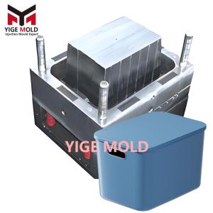
A standard spin mop bucket typically consists of the bucket body, dewatering basket, cover plate, wheels, and drainage system. Its functional complexity translates directly into stringent demands on mold design:
-
Complex 3D Structure: The bucket body commonly features a heteromorphic container design with a square-to-round transition. The interior requires precise molding of guide slots for securing the dewatering basket, reinforcing ribs, and water level lines, while the exterior must form ergonomic handle recesses, wheel mounting seats, and drain valve interfaces. This demands the mold possess the capability to handle complex surfaces and numerous intricate features.
-
High-Precision Fit Requirements: The fit between the dewatering basket and the bucket's central shaft is crucial for efficient spinning and dewatering. This necessitates extremely high concentricity and dimensional stability between the bucket's internal central shaft seat/card slots and the parts formed by the dewatering basket mold, with tolerances typically needing to be controlled within ±0.05mm to ensure smooth rotation, no wobble, and no water splash during dewatering.
-
Dynamic Function and Seal Realization: The bucket's drain valve (common types include piston and flip-top) requires the mold to directly form movable pivot structures or precise mating surfaces to enable on/off functionality and ensure long-term seal integrity, preventing leaks. This involves complex side-core pulling mechanisms and fine-tuned shut-off surface design.
-
The Manufacturing Paradox of Large Size and Thin Walls: To meet practical capacity needs, mop buckets are relatively large (common specifications: height 35-40cm, diameter/aperture 30-35cm). However, to save material, reduce weight, and control costs, wall thickness is continuously reduced (typically 1.8-2.2mm). This characteristic of being "large yet thin" results in long melt flow paths and uneven cooling shrinkage within the mold,极易leading to product warpage, sink marks, or stress cracking, posing an extreme challenge for the design of the mold's gating and cooling systems.
-
Refinement of Appearance and User Experience: As a household consumer product, its appearance must be smooth and aesthetically pleasing. Parting line marks must be minimized and rounded, with no visible weld lines or sink marks. All edges in contact with the user, especially the pouring spout and handle areas, must be smooth and burr-free. This demands the mold cavity to have a very high surface polish grade (usually requiring a mirror or high-gloss finish).
2. In-Depth Analysis of the Mold's Core Structural Systems
A high-performance mop bucket mold is a highly coordinated, precision mechanical system. Its core components are as follows:
-
Molding System: Imparting Shape
-
Cavity and Core: Form the main volume of the product. The cavity determines the bucket's outer surface, bottom, and external features; the core forms the bucket's inner surface, internal ribs, and structures. Due to the bucket's depth, the core is usually a tall "boss," making its structural strength, venting, and ejection design critical.
-
Side-Action Core-Pulling Mechanisms: Used to form undercuts and recesses on the product's sides that cannot be directly ejected in the main mold opening direction.
-
Sliders: Typically driven by angle pins or hydraulic cylinders, used to form external side recesses on the bucket body, such as complex handle cavities, card slots for wheel mounts, etc.
-
Lifters (Angle Lifters): Perform a lateral movement during the ejection process, used to form internal undercuts, such as the undercuts at the ends of reinforcing ribs, internal card slots, etc.
-
-
Special Forming Mechanisms: For designs with threaded drain outlets, a rotating unscrewing mechanism driven by a hydraulic motor or a threaded core insert that is manually or mechanically unscrewed after mold opening may be required.
-
-
Gating System: The Highway for Molten Plastic
-
Given the large size of mop buckets, mainstream designs have fully adopted hot runner systems, with valve-gated hot runners being particularly advantageous.
-
Core Advantages:
-
No Waste: Eliminates cold runners, directly saving 20%-30% in material costs, which is significant for high-volume plastic products.
-
Superior Quality: By using multiple symmetrically arranged nozzles, the melt enters simultaneously or sequentially from different positions on the bucket. This significantly shortens the melt flow path, balances filling pressure, effectively avoids or weakens weld lines at junctions like the bucket bottom and wall, and reduces internal stress caused by uneven flow, fundamentally minimizing product warpage.
-
Process Control: Valve gates allow precise control of opening and closing times, enabling Sequential Valve Gating (SVG), further optimizing the filling pattern to ensure filling proceeds from critical areas (e.g., stress-bearing parts) to less critical ones.
-
-
-
Ejection System: Guaranteeing Perfect Demolding
-
Facing a product with deep cavities, thin walls, and a large surface area, ejection must be balanced in force, smooth, and synchronized.
-
Compound Ejection: Typically combines various ejection elements:
-
Ejector Pins: Widely distributed across the bucket bottom plane and the roots of side-wall ribs. They are numerous and evenly laid out.
-
Blade Ejectors/Strip Ejectors: Used in narrow areas like the bottom of ribs.
-
Sleeve Ejectors: Specifically used to eject tall, deep cylindrical structures on the bucket bottom, such as the central shaft seat, preventing "whitening" or stretching due to high packing force.
-
-
Auxiliary Demolding Techniques: In high-end molds, air channels are often designed into the core. After mold opening, compressed air is blown between the product and the core, using air pressure to break the vacuum adhesion and assist in the smooth ejection of the product. This is particularly important for high-gloss surfaces or deep cavities with minimal/no draft.
-
-
Cooling System: The Control Center for Efficiency and Quality
-
This is the most critical system determining the injection cycle time and product dimensional stability. Uneven cooling is the primary cause of warpage in large, thin-walled products.
-
"Conformal Cooling" Philosophy: The layout of cooling channels must closely follow the surface contours of the cavity and core, especially in areas with thicker walls or concentrated heat (e.g., intersections of ribs, near gates).
-
Layered Multi-Circuit Design: Inside deep cores, "baffle" or "bubbler" cooling is often used, or multiple series circuits are combined to ensure cooling medium effectively removes heat from deep within the core. The cavity section typically uses multiple parallel circuits to ensure an overall uniform temperature field.
-
Material Assistance: In local hot spots, inserts made of highly thermally conductive materials like beryllium copper alloy or thermal pins can be embedded to act as "thermal superconductors" for accelerated heat dissipation.
-
-
Venting System: The Devil is in the Details
-
Due to the bucket's depth, air and plastic decomposition gases are easily trapped at the end of fill and the bottom of ribs, leading to burning, short shots, or surface flow marks.
-
Comprehensive Venting: Vent slots are not only placed on the main parting surface but also extensively at the clearance of ejector pin holes, slider mating surfaces, and insert seams. The depth and width of vent slots require precise calculation to achieve the optimal balance between allowing gas escape and preventing plastic melt flash.
-
3. Manufacturing and Materials: The Foundation of Precision Engineering
-
Precision Manufacturing Chain: Mold manufacturing is a systematic engineering process. High-Speed CNC Milling completes most roughing and finishing of cavities and cores; Electrical Discharge Machining (EDM) handles sharp corners, deep ribs, and fine textures; Deep-Hole Drilling machines complex internal cooling channels; Precision Grinding and Jig Grinding ensure the parallelism and squareness of mold plates and key components; finally, manual Polishing (progressing from coarse stones to diamond paste) achieves the required surface finish.
-
Steel Selection Philosophy: Balancing mold life, cost, and machinability is crucial. Pre-hardened Plastic Mold Steels (e.g., P20/718, NAK80) are the mainstream choice. They come with a hardness of approximately HRC 30-40, can be machined directly, avoiding the risk of heat treatment distortion, and offer good polishability and wear resistance. For applications demanding extremely high wear resistance, corrosion resistance, or ultra-long life, Hardened Tool Steels (e.g., S136, H13) are chosen, undergoing overall quenching and surface nitriding, but with significantly increased cost and machining difficulty.
Conclusion
The mop bucket mold, industrial equipment seemingly focused on a single product, is in fact a micro-engineering platform condensing the essence of modern mold technology. Starting from a precise analysis of a plastic bucket's functional requirements, it transforms plastic pellets into a complex, reliable, and well-finished end product through highly integrated structural design, precisely balanced hot runner and cooling systems, and meticulous manufacturing processes. Its design and manufacturing level directly reflects the mold engineer's profound understanding and comprehensive mastery of material properties, fluid dynamics, heat transfer, and mechanical motion. Behind the mass production of low-cost, high-quality household products stands this precise, reliable, and efficient mop bucket mold, silently laying the foundation for the convenience of modern life and demonstrating the core value and profound impact of the equipment manufacturing industry as the "mother of industries."