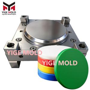
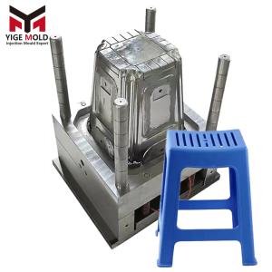
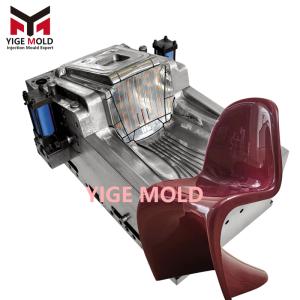
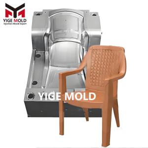
Plastic stool injection mold

Plastic Stool Injection Mold
Product Definition:
A plastic stool injection mold is a specialized molding tool used to produce various types of plastic stools for household, commercial, and industrial applications. The final product must satisfy multiple requirements including ergonomic comfort, structural load-bearing capacity, usage safety, stacking convenience, and cost-effectiveness. Commonly used materials are Polypropylene (PP), Polyethylene (PE), and Polypropylene Copolymer (PP-CO). Its structure typically comprises a seat surface, support legs, and reinforcing ribs, and can be manufactured using either a single-shot, one-piece molding process or a multi-part molding and assembly process.
Detailed Mold Technology System:
1. Core Structural Design Points
-
Ergonomic Surface Design:
-
The seat surface is designed as a slightly concave curved surface (curvature radius R800-1200mm) with rounded edges (R3-5mm).
-
Reverse Engineering Scanning is used to obtain optimal sitting pressure distribution, optimizing the seat thickness gradient (center 3.5-4.5mm, edge 2.0-2.8mm).
-
-
Load-Bearing Structure Optimization:
-
Legs employ a variable cross-section design, thickened to 4-5mm at the root with radiating reinforcing ribs.
-
The junction between the seat and legs uses a topology optimization algorithm to generate a bionic rib network structure.
-
Finite Element Analysis (FEA) must ensure a static load capacity ≥150kg and fatigue testing ≥50,000 cycles.
-
-
Stacking System Design:
-
The bottom of the upper stool and the top of the lower stool feature tapered guide structures (draft angle 3-5°).
-
Stacking clearance is controlled at 0.8-1.5mm, ensuring stable stacking of 5-8 units.
-
2. Gating and Venting System
Gating System Configuration Options:
├── Option A (One-Piece Stool): 4-point valve-gated hot runner system
│   ├── Gate Location: Inside surface of leg roots
│   ├── Runner Balancing: Optimizes individual gate sizes via Moldflow
│   └── Sequential Control: Achieves fill from legs towards seat surface
├── Option B (Multi-Part Stool): Family mold design
│   ├── Seat Mold: Uses pinpoint gates transitioning to cold runners
│   ├── Leg Mold: Uses submarine gates
│   └── Molding Efficiency: Allows 2+2 or 4+4 cavity combinations
└── Venting System:
    ├── Parting Line Vents: Continuous slots 0.02-0.03mm deep
    ├── Insert Vents: Stepped slots 0.015-0.02mm deep
    └── Ejector Pin Vents: Micro-clearance of 0.005mm on pins ≥Φ3mm
3. Cooling System Design
-
Zoned Differential Cooling:
Cooling Strategy Matrix: ├── Seat Area: Conformal cooling channels (3D printed core) │ ├── Channel-to-surface distance: 2.5±0.3mm │ └── Water Temperature Control: 15-25°C (for fast setting) ├── Leg Thick-Wall Area: Fountain cooling + Beryllium copper inserts │ ├── Cooling well diameter: Φ8-12mm │ └── Inlet/Outlet ΔT: ≤2°C ├── Rib Area: Baffle-cooled channels │ ├── Baffle thickness: 1.5-2.0mm │ └── Water Flow Velocity: ≥2 m/s └── Gate Area: Independent cooling circuit └── Temperature Monitoring: Embedded thermocouple -
Thermal Balance Control:
-
Predicts hot spots via mold flow analysis to pre-place cooling elements.
-
Uses mold temperature controllers to achieve a temperature differential: front mold 40-50°C, rear mold 30-40°C.
-
4. Ejection and Core-Pulling System
-
Composite Ejection Mechanism:
-
Uses a hybrid system of nitrogen springs + mechanical ejection.
-
Ejector pin layout is optimized via mechanical simulation to prevent ejection marks and deformation.
-
Implements delayed ejection mechanisms (0.2-0.3s delay) at the seat edge.
-
-
Undercut Handling Solutions:
-
For stools with storage functions (concave underside), uses collapsible core sliders or hydraulic core pulls.
-
Slider movement is equipped with hard stops, with repeat positioning accuracy ≤0.02mm.
-
Manufacturing Precision Control Standards:
|
Control Item |
Precision Requirement |
Inspection Method |
Functional Relevance |
|---|---|---|---|
|
Seat Surface Flatness |
≤0.3mm / 300mm |
Surface Plate + Feeler Gauge |
Ensures seating comfort. |
|
Four-Leg Levelness |
≤0.5mm (rocking) |
Granite Plate + Dial Indicator |
Guarantees stability. |
|
Stacking Fit Clearance |
0.8-1.5mm |
Standard Gauge |
Optimizes stacking performance. |
|
Weight Deviation |
≤ ±2% |
Electronic Balance (5kg capacity) |
Controls material cost. |
Molding Process Window:
1. Material and Process Parameters
Process Parameter Optimization Table:
├── Material: Polypropylene Copolymer (PP-CO, MFR 20-30 g/10min)
├── Temperature Settings
│   ├── Barrel: 175°C / 185°C / 195°C / 200°C
│   ├── Mold: Front 45±3°C, Rear 35±3°C
│   └── Hot Runner: 210±5°C
├── Injection Parameters
│   ├── Speed Profile: Low 15% (gate) → High 85% (main) → Med 40% (end)
│   ├── Pressure Settings: Injection 80-100 MPa, Packing 50-70 MPa
│   └── V/P Switch Point: 98-99%
└── Post-Processing
    ├── Cooling Time: 25-40 seconds (depending on wall thickness)
    └── Sizing Treatment: Placement in sizing fixture for 20 min after ejection
2. Common Defect Prevention
-
Sink Marks: Increase packing time (by 1-2 seconds) on the back of ribs.
-
Warpage: Optimize packing pressure curve, use a three-stage decreasing packing pressure.
-
Weld Lines: Increase mold temperature by 5-10°C, adjust gate location.
Mold Maintenance and Lifecycle Management:
1. Preventive Maintenance Schedule
-
Per Shift: Clean parting lines, check ejector pin return.
-
Every 30k cycles: Replace ejector pins, springs, clean water lines.
-
Every 100k cycles: Inspect slider wear, polish cavity.
-
Every 300k cycles: Comprehensive overhaul, replace guiding components.
2. Life and Economics
-
Mold Life: 800k - 1.2 million cycles (under normal maintenance).
-
Cycle Time: 35-60 seconds/cycle (including robotic part removal).
-
Rejection Rate: ≤0.5% (based on SPC statistics).
-
Investment Payback Period: 8-14 months (calculated for two-shift operation).